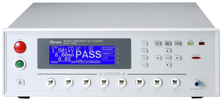
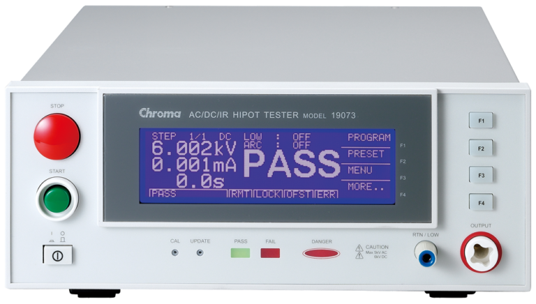
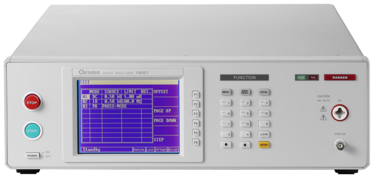
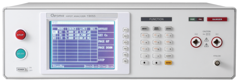
Hipot / Dielectric Strength Test Equipment
A dielectric strength test, commonly called a hipot test, dielectric withstand, or high potential, is a stress test of the insulation of a device under test (DUT).
Such a test applies a voltage to the DUT that is much higher than normal operating voltage; typically 1000V AC plus twice the normal operating voltage. For a household appliance designed to operate at 120 or 240V AC, the test voltage is usually about 1250 to 1500V AC.
A DC hipot test can usually be substituted for an AC hipot test. The best voltage for a DC hipot is normally higher than the AC test voltage by a factor of 1.414. A product that would be tested at 1500V AC would be tested at 2121V DC.
For double-insulated products, the required test voltages may be much higher, such as 2500 VAC or even 4000 VAC for a 120 VAC power tool. The voltage is applied between the operating circuits and the chassis or ground – the parts of a product that a consumer might touch or come in contact with.
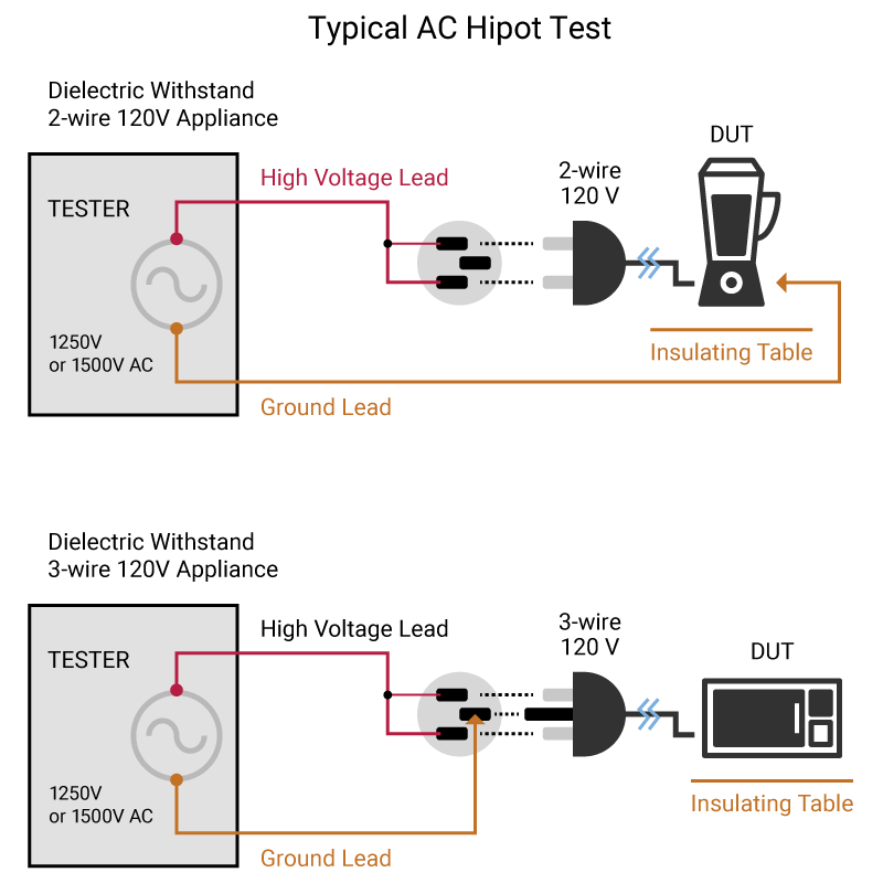
Refer to Figure 5 for typical AC hipot test setup. The setup for a DC hipot test would be identical.
The purpose of the test is to make sure consumers do not receive an electrical shock when they use the product. This typically is caused by a breakdown of the electrical insulation. The test also detects possible defects in design and workmanship that cause components and conductors to be too closely spaced. The danger is that air gaps between conductors or circuit components may become clogged with dust, dirt, and other contaminants over time in typical user environments. If the design spacing is inadequate, a shock hazard can occur after a period of use. By subjecting the product to a very high voltage, the hipot test overstresses the product to the point that arcing may occur if the spacing is too close. If the product passes the hipot test, it is very unlikely to cause an electrical shock in normal use.
Withstanding a very high voltage means that a large margin of protection exists for the consumer. Regulatory agencies usually require a stringent hipot test as a product “type test” before releasing the product for sale to the public and another less demanding test to be used on the production line. As a rule, testing laboratories consider the hipot test to be the most important safeguard for the consumer. They may accept “design” or “type” tests for other types of tests, but always require hipot tests for 100% of the units in a production line.
AC or DC Hipot?
The voltage used in a hipot test can be either AC or DC, depending on the requirements established by the regulatory testing agency. Both have their advantages and disadvantages. The typical rule of thumb used to select an AC or DC test is if the DUT is powered by AC, then use an AC test; if it is powered by DC, use a DC test.
AC Hipot Tests
With an AC hipot test, a long ramp time is usually not required (except with certain sensitive devices). AC testing also has the advantages of checking both polarities of voltage and of not needing to discharge the DUT after testing is complete. AC testing, however, does have some disadvantages. An AC test must consider the effects of both real and reactive current (see Glossary for definition of terms). When you apply an AC voltage, the current that flows is equal to the voltage divided by the impedance. The impedance, however, is complex because it contains both resistive (real) and capacitive (reactive) components.
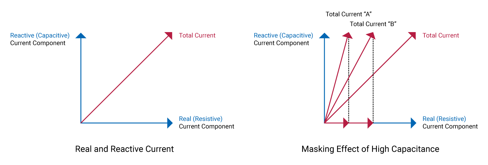
Because these two components of AC current are out of phase with each other, they combine in a complex manner to form the total current, as shown in Figure 6. Since the magnitudes of the two components can be significantly different from each other, the leakage current (the “real” component) of a product with large amounts of capacitance can, with some testers, increase significantly without being detected by the test.
As shown in Figure 7, an increase of 100% in leakage current causes only a very small (1%) increase in total current when the total current has a high reactive component. The tester must therefore be very sensitive to detect a change in total current in a DUT with high capacitance. AC testing at high voltage levels may also degrade some types of insulation. To avoid such problems, most manufacturers try not to exceed the required voltage levels and hold times, and to minimize the number of tests performed on a given product.
DC Hipot Tests
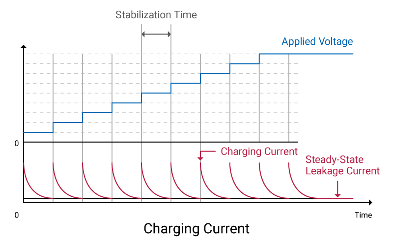
A typical DC hipot test applies a voltage in gradual steps, commonly called ramping, pausing after each increase to allow the capacitance of the DUT to absorb a charge and stabilize. As shown in Figure 8, the current increases sharply after each increase in voltage as the capacitance charges, and then decreases to a low steady-state value. The time required for the charging current to decay after each step is called the stabilization time. Current that flows after the stabilization time has passed represents the leakage current through the insulation. If the voltage steps are too large, the sharp rise in charging current when the step is applied may exceed the high current limit, causing the test to fail prematurely. The magnitude and timing of the steps, therefore, should be carefully matched to the characteristics of the DUT.
Hipot Test – charging currentBy monitoring current flow as you gradually increase the applied voltage, waiting for the charging current to decay, and observing the leakage current (if any), you can detect a potential insulation breakdown before it occurs. If the leakage current suddenly starts to increase over the expected value, an insulation breakdown is likely to occur soon. Interrupting the test at this point can save the insulation from breakdown. The test fails but the product is not damaged and may be salvaged by visual inspection or some other means. Such a test, therefore, can be classed as “nondestructive”. If the product being tested does not have significant capacitance, there is little or no charging current, and the rate at which the voltage is gradually increased can be much more rapid.
Because a DC hipot test charges the capacitance of a DUT, the charge itself can present a hazard to testing personnel that must be removed after the test is over. Remove the stored capacitance by discharging the DUT to ground. Typically, the hipot tester automatically discharges the DUT for the same period of time the test voltage was applied.
No arcing or “sparking” should occur in an insulation stress test. If it does start to occur, the insulation is about to fail. A good tester, therefore, should detect presence of any arcing before real damage occurs.
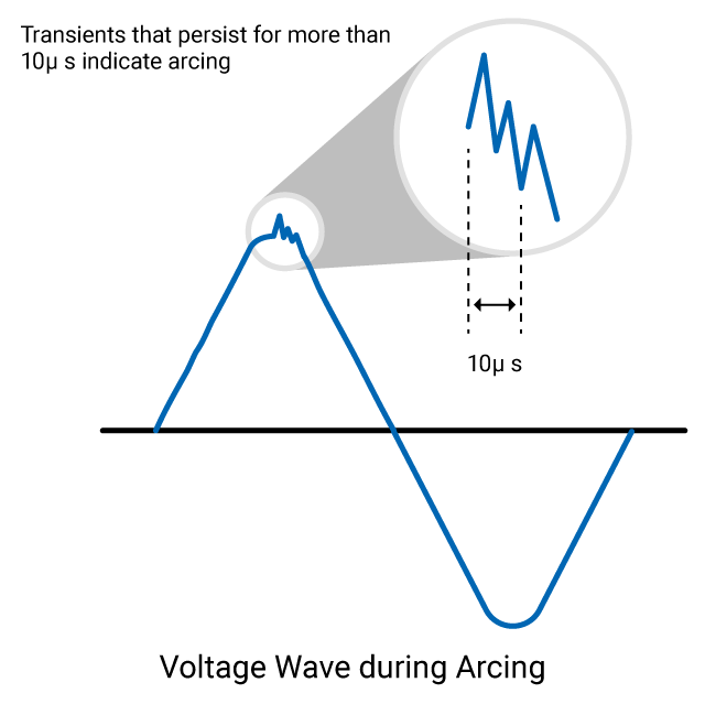
An electrical arc is characterized by very rapid variations in voltage and current (Figure 9). It also produces an audible crackling or “zapping” sound. Because of these rapid changes, arcing can be detected – as soon as it starts to occur – by sensing for the presence of high frequency energy. This can be accomplished through the use of an electrical filter circuit in the tester.
The circuit continuously monitors the current flowing through the DUT (which may be either AC or DC) and checks the magnitude and timing of deviations from normal values. If a high frequency component is found that persists for longer than a specified time, which may be as short as 10 microseconds, the circuit interprets this as an arc and immediately alarms and terminates the test. Arcs that last less than 10 microseconds are not considered harmful. The arc detection level can usually be adjusted to prevent false arc failures caused by environmental influences such as electrical noise. Arcing can be a valuable tool for evaluating the performance of insulation and dielectric barriers within a product. Currently there are no standards that require the use of arc detection in the determination of the safety of a product.
Line Regulation
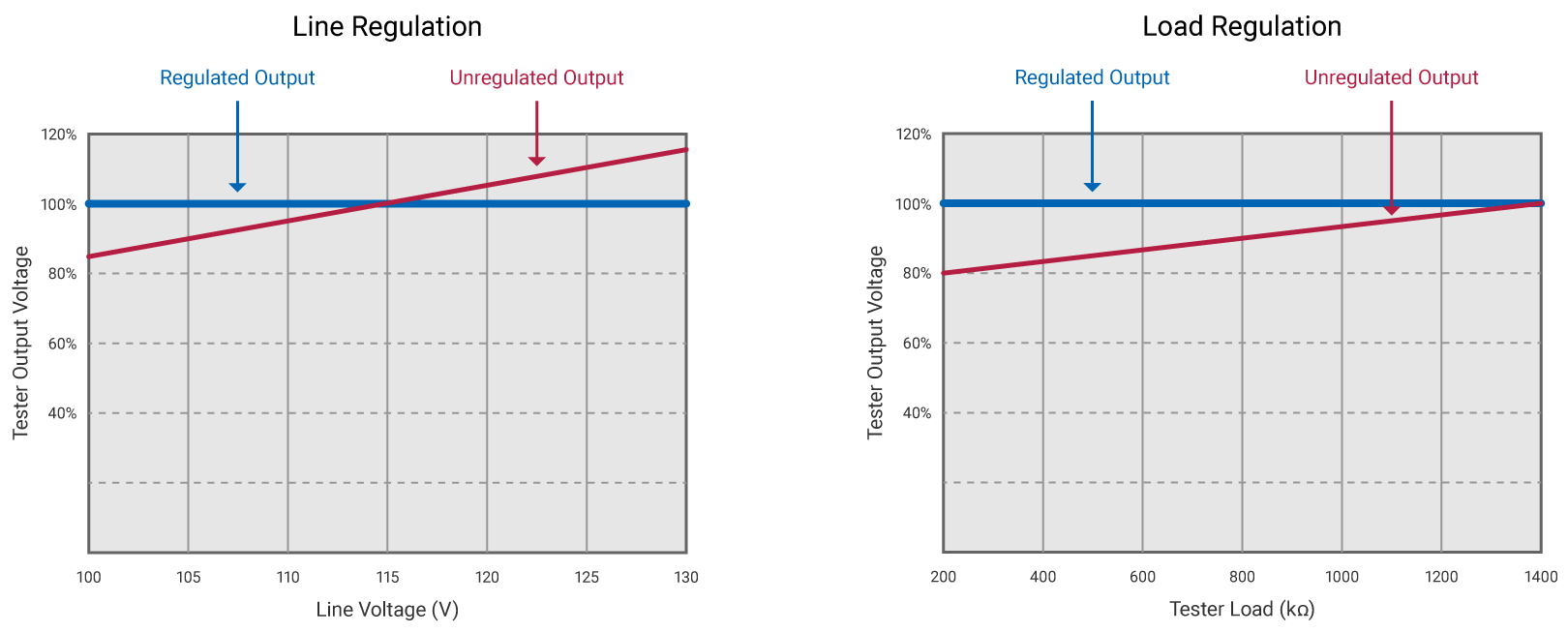
Users should be aware of possible effects on tester performance of changes in line voltage and output load. The line voltage that powers a tester can typically vary by ±5%. Since the tester usuallyincorporates a transformer of some kind to generate its high voltage output, a change in input voltage, unless corrected, can produce a corresponding change in output level (Figure 10). The problem arises if a drop in input voltage causes the output voltage to drop below the level required for the hipot test. If this situation occurs, the tester could pass a DUT that really should have failed, compromising the integrity of the test.
Modern testers, therefore, compensate for load regulation by directly sensing the output voltage and automatically correcting for any variations.
Ramping
With AC hipot testing, high voltage is usually applied directly to the DUT without the gradual stepped increases used with DC hipot testing. This approach, however, can cause potential damage to some types of electrical circuit components. Because of this, some testers use electronic ramping to increase the voltage from zero to the test value smoothly over a period of time.
Agency test specifications require that a tester must produce a pure sine wave output voltage. In earlier systems, every adjustment to the tester that increased the output voltage could cause a distortion, such as a spike or high frequency transient, to appear in the voltage wave produced by the tester. The testers, therefore, did not fully comply with the agency requirements. Modern testers, however, have eliminated this problem by electronically controlling the voltage and maintaining an undistorted waveform over the whole range as it is ramped from zero to the final value. This not only meets the agency requirements but also prevents spikes from damaging the DUT.

Agency requirements specify a maximum current limit for a successful hipot test, but they do not specify any minimum level. Omission of such a requirement, however, means that under some conditions it is possible for a tester to pass defective DUTs.
Setting a maximum (high) current limit tells the hipot tester to shut down when that current level is reached. Any value above the high current limit is considered a Fail and any value below the set high limit is considered a Pass. Setting a minimum (low) current limit tells the hipot tester to shut down if there is not the specified minimum amount of current after the test is initiated.
Any value above the low current limit is considered a Pass and any value below the set low limit is considered a Fail. Refer to Figure 12.
In a properly functioning hipot test setup, a very small current safely flows through the DUT and the associated cables and fixtures. If, however, the circuit is broken because of a faulty fixture or cable connection, the integrity of the test is compromised. Unless the tester monitors for the minimum current, a break in the ground connection can cause the tester to indicate a successful test even though the DUT is defective because the tester is looking at an open circuit and may not even be connected to the DUT. The use of a low limit can also detect if the power switch is in its on position as required for proper testing. A tester that monitors current and sounds an alarm when it falls below a minimum level can detect a break in the test setup circuit and alert the operator immediately.
