LED Driver Testing

Chroma provides LED testing solution which include: programmable AC and DC Sources, high precision Power Meters, and LED Load Simulator specifically designed for LED power drivers. Chroma is also able to provide Automated Test Systems suitable for R&D, QA qualifications and mass production.

LED Power Driver Test Guide

Read more about our LED Power Driver test specification containing test terminologies and their definitions, product categories, test setups, and includes test items such as output performance, ripple current, dimming frequency, etc. 

Testing LED Drivers​

LED Drivers supply the power to light up an LED array. Since LED’s are driven by DC current they require a converter to power them from an AC voltage source. These power supplies have different operating characteristics from most typical AC-DC and DC-DC Power Supplies. They are typically designed as a constant current source due to the light emitting characteristics of the LEDs. Although LED drivers’ functions and characteristics differ from the general switch mode power supply (SMPS), the components used, the design topology, and testing requirements are very similar.

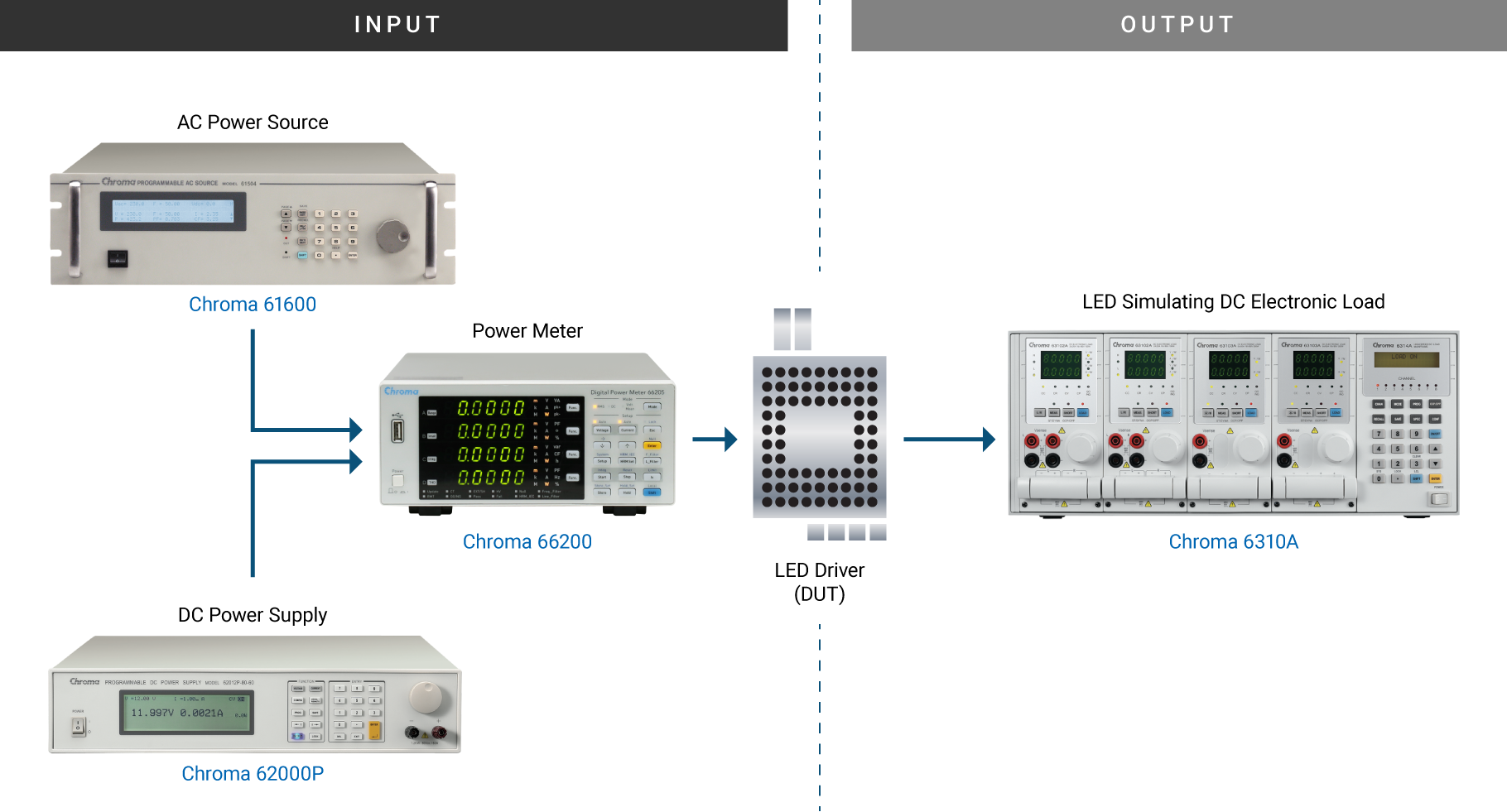
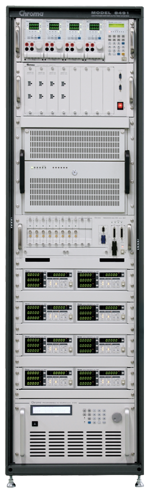
LED Power Driver Test System

Chroma C8000

This test system can test all the input and output conditions for LED Power Drivers consistently and accurately. Programmed routines for a variety of tests fully test the entire specifications for an LED Power Driver and can handle multiple measurements for multiple unit testing. Using Chroma’s Power Pro software, the system is easy to program and data collection for SPC requirements is built right into the software.

The Chroma C8000 ATS is equipped with optimized standard test items for LED driver testing (lighting & TV backlight). The user is only required to define the test conditions and specifications for the standard test items to perform the test.

Digital Power Meter, 30A

(66200) Used for measuring Input Power, Voltage, Current and Surge Current, and Total Harmonic Distortion. For testing LED driver efficiency, we’ve included a built in program for testing to Energy Star requirements.

Low Power Programmable AC Source

(61600/61500) Used for testing the Input Voltage range and transients for LED Drivers. In addition, the AC Power Source is used for Line Regulation and Transient testing and have the ability to generate AC waveforms and non-Sinusoidal waveforms.

Modular DC Electronic Load LED Simulator

(6310A) is the industry’s first LED simulating load for LED driver testing. The 6310A is specifically designed for simulating the unique load conditions of an LED and LED Array. It also has the ability to be programmed for Vf, Vo, Rd and Rd coefficient, making it the best load for simulating a real LED array load when testing an LED driver.

Programmable DC Power Supply

(62000P) Used for the input power to a LED Driver that has a DC Input rather than an AC Input. The DC supply can also simulate the LED Power Driver output for testing an LED or LED Array. The output of our DC sources can be used in Constant Voltage or Constant Current to simulate a variety of LED Driver Outputs. The ability to program the voltage in ramps and steps and a variety of waveforms helps simulate various conditions for the LED Power Driver output.

Why use an LED Simulator to test an LED Driver?

As shown on the V-I curve, the LED has a forward voltage VF and a operating resistance (Rd). LED drivers are usually tested in one of the following ways;

  • Using LEDs
  • Using resistors for loading
  • Using Electronic Loads in Constant Resistance (CR) mode, or Constant Voltage (CV) mode


All the above loading methods each have distinct disadvantages. First, those manufacturers who use actual LED’s as a load run into problems with the aging of the LEDs. Different LED drivers may require different types of LED’s or a number of LED’s. This makes it inconvenient for mass production testing. Second, resistive or linear loads can not simulate the Vf and Rd coefficient of an LED. When using a Typical Electronic Load to test LED drivers, the CR (Constant Resistance) and CV (Constant Voltage) mode settings are used. These settings only can test stable operation and therefore, are unable to simulate turn on or PWM Dimming/intensity control.

In order to thoroughly test an LED driver, we recommend our 6310A Electronic Loads with LED Array Simulation.

Chroma’s 6310A LED Load calculates and simulates the LED characteristics from the Vo, Io, Rd coefficient settings, as shown in the diagram, Vo and Io are not the real loading values.

Compare the actual LED characteristics to the 6310A Load

Figure 2 shows the current waveform from an actual LED.

Figure 3 shows the current waveform from 6310A’s LED mode load function.

Figures 2 & 3, show the start up voltage and current of the LED driver with an LED versus the Chroma 6310A Electronic Load in LED Mode and they are very similar.

Figure 4 shows the dimming current waveform of an LED.
Figure 5 shows the dimming current waveform when using 6310A as a LED load.

Io is determined by the LED driver, if the Io varies from the setting value then Vo will also vary. For example, if Io setting is 100mA, but the LED driver output 110mA, then Vo will also increase. This is different from the standard CC and CV mode.