Yes, all models within the 63800 series can be used together for both parallel and 3-phase functions.
- AC Loads
- 11210 Battery Instulation Tester
- AC Power
- Administration
- DC Loads
- DC Power
- Digital Power Meters
- Hipot & Safety
- LC IR Meter
- Softpanels
- TEC Controller
- Thermal Data Loggers
If the customers UUT voltage is higher than the maximum voltage rating for the 63800 Series of AC Loads can a Step – Down transformer be used?
Yes, A step down transformer can be used to lower the voltage to be less than the maximum rated voltage for the 63800 series AC Load.
What is “Apparent Power”?
Apparent power is a measure of alternating current (AC) power that is computed by multiplying the root-mean-square (rms) current by the root-mean-square voltage. In a direct current (DC) circuit, or in an AC circuit whose impedance is a pure resistance, the voltage and current are in phase. P is the power in watts, Erms is the root-mean-square (rms) voltage in volts, and Irms is the rms current in amperes. But in an AC circuit whose impedance consists of reactance as well as resistance, the voltage and current are not in phase. This complicates the determination of power.
In an AC circuit, the product of the rms voltage and the rms current is called apparent power. When the impedance is a pure resistance, the apparent power is the same as the true power. But when reactance exists, the apparent power is greater than the true power. The vector difference between the apparent and true power is called reactive power. If Pa represents the apparent power in a complex AC circuit, Pt represents the true power, and Pr represents the reactive power.
What is “True Power”?
True power is the power manifested in tangible form such as electromagnetic radiation, acoustic waves, or mechanical phenomena. In a direct current (DC) circuit, orin an alternating current (AC) circuit whose impedance is a pure resistance, the voltage and current are in phase. P is the power in watts, Erms is the root-mean-square voltage in volts, and Irms is therms current in amperes. But in an AC circuit whose impedance consists of reactance as well as resistance, the voltage and current are not in phase. This complicates the determination of power.
In the absence of reactance, this voltage-current product represents true power. But when there is reactance in an AC circuit, the product Erms. Irms is larger than the true power, and is known as apparent power. The vector difference between the apparent and true power is called reactive power, and represents energy alternately stored and released by inductor and/or capacitor.
What is “VA”?
Volt-ampere is a measurement of power in a direct current (DC) electrical circuit.The VA specification is also used in alternating current (AC) circuits, but it is less precisein this application, because it represents apparent power, which often differs from truepower.
In a DC circuit, 1 VA is the equivalent of one watt (1 W). The power, P (in watts) in a DC circuit is equal to the product of the voltage V (in volts) and the current I (inamperes):
P = VI
In an AC circuit, power and VA mean the same thing only when there is no reactance. Reactance is introduced when a circuit contains an inductor or capacitor. Because most AC circuits contain reactance, the VA figure is greater than the actual dissipated ordelivered power in watts. This can cause confusion in specifications for power supplies.For example, a supply might be rated at 600 VA. This does not mean it can deliver 600watts, unless the equipment is reactance-free. In real life, the true wattage rating of apower supply is 1/2 to 2/3 of the VA rating.
When purchasing a power source such as an uninterruptible power supply (UPS) for usewith electronic equipment (including computers, monitors, and other peripherals), be surethe VA specifications for the equipment are used when determining the minimum ratingsfor the power supply. The VA figure is nominally 1.67 times (167 percent of) the powerconsumption in watts. Alternatively, you can multiply the VA rating of the power supplyby 0.6 (60 percent) to get a good idea of its power-delivering capability in watts.
What is “VAR (Volt-Amp-Reactive)”?
Magnetic loads, such as motors, can draw more VA power than actual real power. The extra component is called a VAR. A VAR is basicallymagnetic power, which causes a phase shift between voltage and current curves. This phase shift between voltage and current reduces the overlap between the two curvesand effectively delivers less power to the loads.
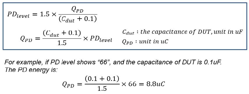
What is the relation between PD level and Coulomb?
Below equation shows the correlation between PD level and PD energy. Higher PD level comes with higher PD energy.
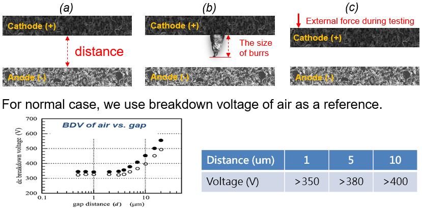
Do you have a chart for testing voltage vs. insulation distance?
There are several main factors affecting the test voltage including:
The Definition of PD
PD is an abbreviation of partial discharge. It means the fast transient of voltage or current.
Is the gap/test voltage relationship the same for all know LIB chemistries?
Yes. As we mentioned before insulation test for a dry-cell should be a check of the distance between electrodes, not the resistance value measurement. Chroma 11210 supports following well known material of LIB cell including LiCoO2, LiMnO2, LiFePO4,and LiNiO2.
As we know Burrs happened in Cathode (+) Al plate, and the information from theresearcher of B4T Mr. Sigit it can appear and or grow after Charge discharge process,can the burrs also happened in Anode Plate?
The burrs are caused by the electrode cutting process. Both current collectors (Al &Cu) may have the issue. In Chroma presentation file, the burrs on Al plate are emphasized because the shortcircuit of Al-anode is more dangerous compared with Cu-cathode.The one grows on anode during charge-discharge process should be called “lithiumdendrite”. It also can cause short circuit issue by damaging the separator.
Do you have any document about WV Test? Or could you please explain more about this function?
WV test mode is mainly used for the DUT like: MLCC, aluminum foil, diode and otherapplications. This mode is to measure whether the DUT can be charged to the voltage point that isalmost get to BDV. (BDV is not used because we don’t want the DUT to be destroyed)Set the upper limit of voltage and charge current first, when the leakage current isequal to the constant charging current, the voltage will be maintained at a certain level.If the DUT is able to be charged to the upper limit of the voltage, it will judge PASS;otherwise, if the voltage cannot reach to the set voltage, it will judge Fail.
Why we consider BDV of air, but not separator.
Separator is porosity, mix of air and plastic and/or ceramic. Normally, separator andceramic with stronger withstanding voltage, therefore a weaker insulator “air”should be considered for the lowest WV test voltage.
Minimum safe Insulation “distance”
No matter how thick the separator is used, after Jelly Roll wound, the effective distancebecomes shorter because the surface of the electrodes are rugged, and some smallparticles/burrs may break through “PART” of the separator (that is why most of LIBJelly Rolls BDV are much lower than the separator’s original BDV; 600V~1,000V perour experience for a normal jelly roll). Point is, what is the considered SAFE insulation distance, which is able to resist thefurther inflation of the cathode while battery cell is being charged. The test voltageneeded for finding the insufficient insulation distance, of course MUST at least higherthan the air BDV at this gap distance
Refer to the user manual of 11210, I would like to know why the worst case open circuit test set up for Null function is connecting the +ve terminal to DUT end while leaving the -ve terminal open ( Red terminal ) . Why not reverse ?
11210 uses AC signal to get voltage counts. If terminals are null, 11210 gets high voltage counts ; if +ve terminal is connect to DUT and leave -ve terminal open, 11210can eliminate the effect of parasitic capacitance. If -ve terminal is connect to DUT and leave +ve terminal open, there are still parasitic capacitors but contact check circuit won’t read the parasitic capacitors. So if users follow the suggestion in user manual,11210 can eliminate the effect of parasitic capacitance. Then 11210 will work well in contact check function.
Reverse connection will not happen this situation.
Why VPD and IPD detection function cannot be enable when LC range is auto?
The auto range is mainly used to finding out the suitable testing range. After finding out the suitable range, the unit will use it as the best range for testing. The main reason is that the unit will produce inrush current, when changing ranges which will affect the result of the measurement precision and cause measurement errors of VPD and IPD. Therefore, these features are not supported in auto range mode.
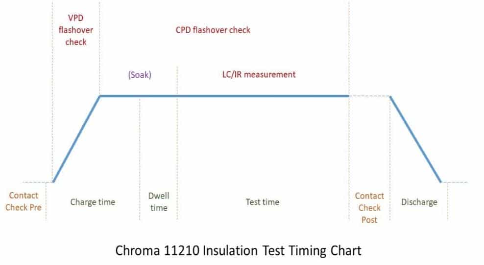
Do you have 11210 Timing Chart?
Can the device perform a test with a CC of 50mA at 1kV?
Yes. Chroma 11210 is designed for Lib cell and capacitor. Normally, the LIB has larger capacitance, so it needs larger charge current. Chroma 11210 can support up to 50mAin charge current and maximum voltage is 1,000V.
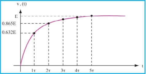
Does test voltage and dwell time vary from mAh coin cells to 100Ah pouch andprismatic cells.
Test voltage does not relate to capacity of battery, however it relate to the distance between electrodes, the external force on pouch type cell, and the particle/burrs on the jelly roll. Dwell time is set for measuring data in stable period. Customer can set any number between 5ms to 99.9sec depending on there product. According to the below chart,“5 times RC constant time” can achieve stable status on Capacitive loading.
What will happen if we reverse the battery polarity in 11210 testing?
Before electrolyte filling, there is no chemical reaction between cathode and anode. Therefore, the testing of reversed polarity DUT shall be without any safety issues and has the same results.
PD test Voltage is selected based on BDV test. Is 50% of the BDV Max Voltage test a good test Voltage for customers manufacturing test ? How do we explain this to customers, is there any theory to why we select 50% versus 30% or 80%?.
The test voltage is decided by customer. the test voltage relates to the distance between anode and cathode which also close to (not equal to) the thickness of separator. So considering the separator and the process for LIB cell testing, we normally suggest customer to set test voltage >350V.
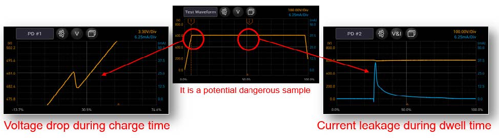
Why does PD will have occurred many times?
The general battery separator is not a single RC circuit but is composed of many RC circuits. And every pore in the separator is an RC. Although the Voltage reaches 600V, there are still have many variations of electric potential in pores. Therefore, the LC value will gradually decrease and PD will occur in the CV mode phase.
Is it possible that PD abnormal occurs, during the CC discharge phase?
Theoretically, it won’t occur. Because the electric intensity will continue to decrease.
What is the purpose to do contact check post?
In case of the leaving timing of probe in some automatic machine is not adjusted and leaving too early. If so, the LC measurement will be 0, which will be judged as a good insulation product.
Discharge time can be setable?
Our discharge uses the internal discharge circuit to automatically discharge to a low enough voltage then send out the ACQ Over signal (the probe contacts can be removed). The time of discharge depends on the capacitance of the DUT.
How does a failure show up on your tester?
There are three indicators on the tester to show the failure.
1. Screen: The failure message would show on the bottom of screen with a red banner.
2. LED: The FAIL LED on the front panel also shows the failure message.
3. Handler: For remote control, handler on the rear panel support different types of failure message.
Are there any differences between testing with AC or DC voltage?
To do the IR measurement on capacitive load, the AC part of test signal will cause additional charge-discharge current to DUT. If doesn’t handling well, it will cause additional measurement errors. Chroma 11210 adopts linear power supply and cascade architecture which effectively reduces the impact of capacitive load measurement error.

Why does CC mode only detect VPD?
In CC charge mode, it is not easy to detect the abnormal current, and the voltage will change significantly when PD occurs, so only VPD is detected.
Why does CV mode only detect CPD?
In CV charge mode, it is not easy to detect the abnormal voltage, and the current willchange significantly when PD occurs, so only VPD is detected.
Which will affect the measurement precision?
The charge current is constant during CC mode, but voltage drop can be captured, so why VPD occurred in CC mode. In the other hand, CPD can capture the leakage current during CV mode. Our analyzer card can shows the waveform in both voltage and current at whole test cycle.
How do I select an AC source power rating for an application?
How to select an AC source power rating for an application
Use the following information for selecting an AC Source that is appropriate for the application.
|
Specification |
Description |
|
Pout: |
The maximum possible output power of the power supply |
|
Eff: |
The efficiency of the power supply |
|
PF: |
The input power factor of the power supply |
|
Vin_low: |
The minimum input voltage |
|
CF_I: |
The crest factor of the power supply’s input current |
|
Ipk_need: |
The repetitive peak current needed from the power supply |
|
Ipk_ac: |
The repetitive peak current that the AC source can provide |
|
CF_ac: |
Crest factor defined in the AC source |
|
Irms_ac: |
AC source’s maximum output R.M.S. current of the respective voltage range |
Select an AC source with a power rating for which Ipk_ac is greater than Ipk_need
Ipk_need = Pout / Eff / PF/ Vin_low ) x CF_I
Ipk_ac = Irms_ac ( range of Vin_low ) x CF_ac
Example:
Assume: Pout = 300 W, Eff = 0.7, PF = 0.55, Vin_low = 90 V, CF_I = 4;
Ipk_need = (300/0.7/0.55/90)x4 = 35A
Given the above, the repetitive input current required will be 35A.
(35/3) x 90 = 1,050
If the AC source outputs CF_ac = 3, then the user must select an AC source which is able to deliver 11.7 Arms current under 90 V output. Therefore the user should use a 1,200VA AC source to test for this requirement.
Why are some of Chroma’s products painted a different color even though they are the same model?
In 2011, Chroma implemented changes in production to standardize colors in order to maintain consistency throughout the entire line of product families. This change is cosmetic only.
When operating (3) of the 61605’s in 3 phase mode can the Phase angle between phases be programmed for phase angles other than 0, 120, 240 Degrees?
YES, the Phase angles can be set independently for each phase see 61605 model ac power source User Manual sections 3.7.2 & 3.7.5 for manually setting the Phase Angle Degrees, see section 7.6.2.5 for instructions on using the SCPI commands for programming and using the remote interface to set the Phase Angle Degree. This is also applies to the 61601, 61602, 61603, & 61604.
If current limits can be specified in the 54100 TEC controller, what are the ranges of and granularity of these current limits?
The range of current limit for both polarities is from 0 to the maximum output, which is 8 A for 54115-24-8 or 12 A for 54130-27-12. The setting resolution for current limit is 1 mA; however, the current won’t be exactly limited down to 1 mA accuracy. 0.1 A error between current limit setting and real current limit can happen. Please note the purpose for current limit is for safety and protection, not for precise current control.
What Chroma AC Sources can be used to simulate the Transients defined in IEC standard’s 61000-4-11 etc.?
Chroma 61500 series of AC Sources can simulate voltage dips, short and variations defined in IEC 61000-4-11. It also has the ability to simulate Harmonic and Inter-Harmonic distorted waveforms as defined in IEC 61000-4-13. The Chroma 61700 series of 3 Phase AC Sources has an optional Transient Voltage Output Function (A617002)
What are the significant differences between the 61600 and 61500 series AC power sources?
The 61600 and 61500 function the same, however, the 61500 AC power source is equipped with more features. It allows you to compose different harmonic components to synthesize your own harmonic distorted wave-shapes. Features included are power line disturbance simulation, programmable output impedance, comprehensive measurement functions, harmonics & inter-harmonics wave-shape synthesis, voltage dips and variation simulation, and high output current crest factor.
What are the power measurement capabilities of the 61800 Regenerative Grid Simulator?
The 61800 Regenerative Grid Simulator is identical to the 61511 in all measurement capacities.
What are the Input Voltage configurations for Chroma AC Sources?
Chroma AC Sources can be ordered with various input voltages and can be configured for Single Phase/3 Phase Delta/3 Phase wye.
Is there a remote command for setting the 3-phase mode of a Chroma 61601 to ‘Master’?
Yes. Take the following SCPI commands for example:
SER:STATE MASTER
SER:STATE?
INST:DEGR, 0-359.9
INST:DEGR
How to setup “single phase” or “three phase” output with 61500/61600 Series AC Power Sources.
The 61511/12, 61611/12 AC Power Sources all have the same type of output terminations. The output can be “Three Phase” or “Single Phase” selectable. This allows the customer to use their system as follows:
- 61511 or 61611: “Three Phase” Output Maximum Power 4Kw per Phase (12Kw total)
- 61511 or 61611: “Single Phase” Output Maximum Power 12Kw
- 61512 or 61612: “Three Phase” Output Maximum Power 6Kw per Phase (18Kw total)
- 61512 or 61612: “Single Phase” Output Maximum Power 18Kw
The output can supply Three Phase” or “Single Phase” power. To select “Three Phase” or “Single Phase” output you simply press the “Phase” button on the front panel. The drawing below shows the Output Terminal Block including the Remote Sense Terminal Block. For “Three Phase” the Output connections are Ø1, Ø2, Ø3 with Neutral (N) and Ground. For “One Phase” the Output connections are Line (L) (Ø2) and Neutral (N) and Ground.
How many AC sources can be combined with the A615104: Input/Output terminal fixture?
2 sources: A615104, 3 sources: A615105
Does the 61800 series produce DC Offset or Pure DC power?
The 61860 regenerative grid simulator can be set to both AC + DC mode (DC offset) & DC output mode (pure DC). The maximum DC output capacity is 10KW/424Vdc/50A per phase.
Can the 6430 AC Source input be 208, 220, 230, or 240Vac?
The 6430 input voltage in the US requires a voltage between 190 to 250Vac. The AC Input to the 6430 AC Source goes directly to a Bridge Rectifier and creates a DC Bus. Since the Input is isolated from Ground it can be connected as Line /Phase to Neutral or Line/Phase to Line/Phase. In the US there are 4 common voltages in this range. They are:
- 208 Vac which is line to Neutral
- 220 Vac which is Line to Neutral
- 230 Vac which is Line to Line
- 240 Vac which is Line to Line
Any of these will work to operate the Chroma 6430 AC Source. The Inputs of the 6430 are isolated from Ground so it is OK to connect a Neutral or a Phase to the Input terminal labeled N.
Can I measure the instantaneous voltage and current given by Chroma Programmable AC Source (acquire the data seen in view mode)?
Our AC Sources have the ability to measure Peak Current, & Surge Current and Vrms. If you want to see the actual Waveform you would need to use an Oscilloscope. Below is a list of the measurements our AC Sources can make.
- Voltage in Volts
- Frequency in Hertz
- Current in Amperes
- True Power in Watts
- Crest Factor
- DC Composition measurement readings of Voltage in Volts
- DC Composition measurement readings of Currents in Amperes
- Peak Current measurements in Amperes
- I surge, only measured from the occurrence of output transition as defined in 3.5.8.
- Apparent Power in Watts
What is “Apparent Power”?
What is “VAR (Volt-Amp-Reactive)”?
What is “VA”?
What is “True Power”?
Does Chroma’s Softpanel software support Windows 7 32-bit or 64-bit?
Chroma’s Softpanel software supports Windows 7 OS in 32-bit & 64-bit mode.
Chroma 6310/30 Softpanel
Chroma 6310A/30A Softpanel
Chroma 63200 Softpanel
Chroma 63472 Softpanel
Chroma 63600 Softpanel
Chroma 63800 Softpanel
Chroma 62000P Softpanel
Chroma 62000H Softpanel
Chroma 62000B Softpanel
Solar Array Simulation Softpanel
Chroma 61500 Softpanel
Chroma 61700 Softpanel
Chroma 6400 Softpanel
Chroma 6500 Softpanel
Aerospace Softpanel
Chroma 66200 Softpanel
Power Efficiency Test Softpanel
We also suggest you install the right driver listed: NI VISA 4.1, NI CVI
6.0, NI IVI 1.83
What is the minimum applied voltage necessary to maintain either full current or full dynamic load settings?
The 63600 Loads Minimum Applied Voltage across the Load Terminals required to maintain Full Current load settings are:
- 63610-80-20 Minimum applied Voltage of 0.5V to maintain 20A Load
- 63630-80-60 Minimum applied Voltage of 0.5V to maintain 60A Load
- 63640-80-80 Minimum applied Voltage of 0.4V to maintain 80A Load
- 63630-600-15 Minimum applied Voltage of 2.0V to maintain 15A Load
The Load will continue to conduct current to a much lower voltage with some de-rating of current see chart below:

The 63600 Loads Minimum Applied Voltage across the Load Terminal required to maintain Full Dynamic load settings are:
- 63610-80-20 Minimum applied Voltage of 1.5V to maintain 80 Amp Pulse Current at 20KHz
- 63630-80-60 Minimum applied Voltage of 1.5V to maintain 60A Load Pulse Current at 20KHz
- 63640-80-80 Minimum applied Voltage of 1.5V to maintain 80A Load Pulse Current at 20KHz
- 63630-600-15 Minimum applied Voltage of 3.0V to maintain 15A Load Pulse Current at 20KHz
The Load will continue to conduct current at a lower voltage with a reduced current setting (Load 1 & Load 2) and increased Time (T1 and T2) see chart below:

For more information, refer to the datasheet or user manual.
The 6310A Load Modules can be used in the old 6310 mainframes but they will lose the newer features.
This is because the 6310A Series mainframe has the new features built in to the hardware and firmware to control the 6310A Series DC Load modules new features. The 6310 do not have this.
When regulating voltage, is the measured voltage read the actual voltage, or is it the initial desired voltage?
Yes, when you send the “measure” command to instrument, you can read the actual voltage. And when you send the “fetch” command to instrument, you can read the value from buffer.
When regulating current, is the measured current read the actual current, or is it the initial desired current?
Yes, when you send the “measure” command to instrument, you can read the actual current. And when you send the “fetch” command to instrument, you can read the value from buffer.
What’s the difference between the 6310A series and the 63600 series?
The 63600 series is a high feature electronic load. In a nutshell, the 63000 series can be loaded with 5 modules rather than 4 providing more power and has three unique features: constant impedance (CZ) mode, digitizing functions, and three current ranges per load. The 6310A however, offers an LED simulating load that is exclusive that series. View our a Chroma DC Loads comparison chart.
What is the significance of having “three current ranges” in your loads?
A third, low current operating and measurement range has been designed into the 63600 DC Loads to provide solutions for emerging sleep, idle and standby mode testing required by Energy Star consumer electronics. This capability eliminates having to use complex and unique test bench equipment. Ideal for all types of consumer electronics when precision current settings and measurements are required at milliamp and microamp levels.
What is the sampling rate of the current, and voltage measurements?
63600 series DC Loads measures the current and voltage with each 2us, but the measurement is depend on the window time as user’s define. 63200 series DC Load measures the current and voltage with each 20ms, and 62000P series DC Power Supply measures the current and voltage with each 200ms.
What is the response time of the current, voltage, and power regulation, and through what interface?
Through GPIB interface, the response time is about 35ms in 63200 series, 3ms in 62000P series DC Power Supply (with USB version, if not is 20ms), 3ms in 63600 series DC Loads under CC mode, 3.6ms under CR mode, 6.8ms under CV mode, 3.6ms under CP mode.
What is the purpose of the CZ mode on the 63600 series DC Load? Can an example be provided?
Constant Impedance mode or CZ mode improves the loading behavior of constant current and power making the loading current more realistic. You can specify the values of a series R and L as well as a shunt R and C. In this mode, the minimum loading current transient time is 400 µs.
What is the power consumption for the Chroma 63205 DC LOAD? During normal operation, used as a load for 54V, 100A. Does it need 3-phase connection?
The 63200 DC Load is a LOAD. The Load gets its current from the source that is hooked to the LOAD Connections. The 120/240 Vac input to the load is only used to power the Fans, and Bias Power Supply to control the Load and does not require power greater than 150Watts. The Power is from what ever source your customer is attaching to the Load Terminals.
No, it doesn’t need a 3-phase connection. It’s a simple NEMA plug.
What is the lowest operating voltage of Chroma’s DC Loads?
Chroma’s DC Loads are among the best in the industry for low voltage applications. Each of Chroma’s DC Load families have a published derating profile showing at what voltage the loads begin to derate. As an example, Chroma’s Model 63600 DC Load will draw full current down to approximately 0.4VDC and then linearly derates to about 100mV.
The differences between the 6310 versus 6310A are listed in the attached pdf file
Download the 6310 vs. 6310A comparison.
The 6310 Load Modules can NOT work in a 6310A mainframe
This is because since 6310 series release, there are hundreds of load module F/W in the field. It’s difficult to control what module F/W is going to work with new 6310A series DC Load mainframe. So the 6310 Load Modules will NOT work in a 6310A series mainframe.
I am testing a fuel cell and need to draw a large amount of current near zero volts, how can I do this with Chroma’s electronic loads?
In a previous FAQ the topic of the load’s ability to draw full current down to low voltage levels is addressed. However, if even lower voltages are required user’s may use a dc power supply in series the the load, effectively floating the load above ground. This technique will allow full current to be draw at zero volts. See Chroma’s application note on this subject for further details and hook up information.
How well are current and voltage measurements synchronized (are there any time delays) and how does this change under different operating modes (current, voltage, or power regulation)?
The 63600 series DC Loads measurement is synchronized, and the 62000P DC Power Supply and 63200 series DC Loads are not. The delay time is 10 ms in 63200 series DC Loads and 100ms in 62000P series Power Supply. ( The time is the same under different modes.)
How to set your 63640-80-80 Load modules for 221Amps at 1V in Constant Resistance Mode.
Step 1: Set the ALL_RUN Feature to ON it is located in the SETUP menu to access the SETUP menu press the ADVA and ENTER keys simultaneously. This must be set on each of your loads.
Step 2: Set the Range to Low (L) by pressing the RANGE key until the (L) indicator is lit. This must be done on each load.
Step 3: Set the CR Mode by pressing the MODE key until a small CR appears on the Load Display. This must be done on each load.
Step 4: Set the Resistance on loads 1 thru 4 to 0.02Ω then on Load 5 set the resistance to 0.05Ω.
When paralleling 5 of the 63640-80-80 Loads you will need to set each load individually. You can not use Master/Slave Mode, you will be limited to set the resistor value to 0.01Ω and can’t set the 0.045Ω needed to achieve 221Amps at 1Vdc. Since you want 221Amps you can set (4) of the loads to CRL and 0.02Ω and set one load to 0.05Ω. To synchronize the loads to turn on and off together you can go to SETUP and select ALL_RUN and set it to ON. You will need to set this on each load module. This will give you a total current of approx. 220Amps at 1Vdc. The Loads you have can only be set to 0.01Ω minimum in Constant Resistance Mode Low Range (CRL).
How much current ripple (noise) is induced on the output by Chroma’s loads?
Ans; injected ripple on the UUT’s current waveform is extremely low, typical values are in the range of 2 microamps (as measure on the 63610-80-20 module using a battery as the current source)
How do you set up the advanced feature “Timing” on the 63600 DC Load module?
The following “Application Note” covers this topic in detail, download the “63600 DC Load Timing Measurements” application note. If you have any further questions please contact our Service/Support team.
How are LED Drivers typically tested?
LED drivers are usually tested in one of the following ways:
- Using LEDs
- Using resistors for loading
- Using Electronic Loads in Constant Resistance (CR) mode, or Constant Voltage (CV) mode
However, all the above loading methods each have distinct disadvantages. First, those manufacturers who use LED’s as a load run into problems with the aging of the LEDs. Different LED drivers may require different types of LED’s or a number of LED’s. This makes it inconvenient for mass production testing. Second, resistive or linear loads can not simulate the Vf and Rd coefficient of an LED.
When using a Typical Electronic Load to test LED drivers, the CR (Constant Resistance) and CV (Constant Voltage) mode settings are used. These settings only can test stable operation and therefore, are unable to simulate turn on or PWM Dimming / intensity control.
What is “Apparent Power”?
What is “VAR (Volt-Amp-Reactive)”?
What is “VA”?
What is “True Power”?
Having problem with Softpanel, indicating Error Message “Error 7” and or “Error 8”?
Some of the Chroma Softpanels require running with Administrator permissions. The Readme Text files included with the Softpanels will include notes regarding this. Administrator permissions are needed to access the Windows Registry and to Create Files. To change the settings you can right click on the Softpanel Icon and go to Properties and then select the Compatibility tab, under Privilege Level (Windows 7) or Settings (Windows 10) select “Run this program as an administrator. See screenshots below.
If you have further issues or need more assistance please contact the Chroma Service department.


Do Chroma's 62000H Series DC Power Supply have a constant power operating mode? Meaning the supply outputs a precise power by adjusting the current and the voltage.
The 62000H Series DC Power Supply do not have a constant power feature. Only constant current (CC) and constant voltage (CV).

We use your 62000B-6-1 mainframe, 62015B modules & a 620007 supervisory unit in a factory tester which is required to be calibrated. Does each 62015B need calibrated or just the mainframe, or just the supervisory unit?
Yes, the Load Modules are calibrated not the Main Frames.
What DC Power Supply is capable of producing +100V and -100V at 5A each, with isolated outputs?
Our 62000P Series DC Power Supply has floating outputs and can be used as a positive or negative voltage source. They can also be connected in series to create a positive and negative output with a common ground.
What is the maximum DC output voltage Chroma has available in our Family of DC Power Supplies?
The 62000B series DC Power Supply Maximum Output Voltage is 150Vdc (62015B-150-10), The 62000H series DC Power Supply Maximum Output Voltage is 900Vdc (62050H-900/62100H-900/62150H-900), The 62000P Series DC Power Supply Maximum Output Voltage is 600Vdc (62012P-600-8/62024P-600-8)
What is the significance of the constant power operating envelope provided by Chroma’s 62000P series?
Constant power operation means that, unlike conventional power supplies, the 62000P series DC Power Supplies can provide higher current levels as the output voltage is reduce along a constant power curve. Therefore, high voltage/low current and low voltage/high current UUTs can be testing using one power supply instead of two or three conventional supplies saving cost and space.
Why doesn’t the A620006 rack mount kit for the 62006P – 62024P DC Power Sources fit initially?
This is the correct part number (A620006) for the 62024P-600-8 DC Power Supply, but the reason why the rack kit will not initially fit the DC Power Supply is because a minor adjustment needs to be made to the side edge of the DC Power Supply (see picture below) prior to mounting the rack kit. there is a small adhesive sticker that needs to be removed. The only tools that you will need to make the adjustment are, a small exact-o knife or a small flathead screw driver.

What is “Apparent Power”?
What is “True Power”?
What is “VA”?
What is “VAR (Volt-Amp-Reactive)”?
Can the 66200 Series Power Meters be Used for DC Power Measurements?
Yes, The Measurements for Voltage, & Current can be used for DC with the same accuracy and resolution as the AC Measurements in 60Hz Specification.
What are the electrical characteristic parameters or quality reliability tests related to inductors? What are the definitions of the parameters? What are the purposes of the tests?
- Inductance (L) and the drop caused by DC bias current:
“Inductance” is the ratio of voltage to current-time gradient. (e = Ldi/dt) The purpose of measurement is to check permeability (μ), size, integrity of core and coil turn. The purpose of applying DC bias current is to check magnetic saturation characteristic of core. - Quality factor (Q):
“Quality factor” is the ratio of inductive reactance (X) to alternating-current resistance (ACR). (Q = X/ACR) About the purpose of measurement, please refer to “inductance” and “alternating-current resistance”. - Direct-current resistance (DCR):
“Direct-current resistance” is the resistance of copper wire. The purpose of measurement is to check soldering, wire material, coil turn, wire length, and wire breaking. - Alternating-current resistance (ACR):
“Alternating-current resistance” is the equivalent resistance including not only copper wire resistance but also hysteresis and eddy current losses. The purpose of measurement is to check copper wire and hysteresis, insulation characteristics of core material. - Impulse winding test:
“Impulse winding test” is a reliability test by analyzing the decay waveform caused by applying an unharmful, rapid, and low-energy impulse voltage across wound components. The purpose of test is to check lacquer and insulation material between turns and layers for detecting insulation fault.
What is Ground Bond Testing?
Ground protection consists of two kinds of test method: Ground Continuity test (GC) and Ground Bond test (GB). The purpose of ground protection test is for protecting users from electrical hazards as touching equipment when unsuitable current is created and flows to the earth.
Why do we need real current function in AC Hipot test?
Please notice that may has difference between total current and real current cause by partly internal capacitive reactance. The current is outputting, if capacitive reactance is higher and reactive is higher, this makes real current lower relatively. If the user can’t measure output current accurately, it will cause a blind spot in testing.
Why do we need ramp time in DC Hipot test?
DC hipot test usually need to add ramp time and fall time, because mostly DUTs are with capacitance and causes charging current generated(figure 3). For charging current steady, ramp time is needed for buffering then leakage current won’t over high because of charge current and judge as FAIL.
Why do we need fall time in Hipot test?
Because hipot test will cause DUT discharge, thus need a period of time for discharging after hipot test is ended. A fine hipot test equipment will descrease fall time to the minimum and mark danger warning before reaching discharge standard for protecting the testers from electrical shock.
Why do we need Auto Gain Compensation?
The test voltage of standard is the mainly factor for judging good product in hipot test. A lot of hipot test equipment convert low voltage into high voltage by transformer then output it, but internal impedance of instrument will cause divider especially in some bad quality hipot test equipment, its actual output voltage can’t reach safety standard. For avoiding error to judge as good product and cause unnecessary trouble, fine hipot test equipment will auto gain compensation to modify and compensate voltage to needed voltage value and design the voltmeter on the output terminal for measuring accurately whether output voltage is insufficient.
Why do the electrical safety test operators need more Training?
All personnel of operating test equipment need to accept basic electronic theory training to realize the effect of current on human body and how to avoid electrical shock, familiar with test environment and precaution for emergency condition occurred. Some test equipments are with interlock function to prevent improper operation. When the personnel realize the previous described items then to explain operation procedure and test purpose about the condition of no good product and test fail occurred. Since the safety tests mostly are high voltage or mass current test, the test personnel should be pay more attention while testing.
Why do products need to undergo electrical safety tests?
The obvious answer is that products are regulated to protect consumers and operators from shock hazards. Shock hazards exist when a potential voltage and current are accessible to the operator with respect to earth ground. Electrical safety tests occupy very little time on the production line, but reduces the risks to operator and consumer considerably.
Why do I need a fast discharge circuit in an electrical safety tester?
Almost all DUTs are equipped with a charged capacitor when testing DC Voltage. To avoid electrical hazards it is necessary to discharge the capacitor to a regulated voltage value at the end of the test. However, the higher capacitance value, the longer it takes to discharge, directly impacting the efficiency of the process. Our safety test equipment includes a fast and reliable capacitor discharge circuit to ensure production efficiency and safety.
Why are leakage current tests so important in Medical Equipment Safety Standards?
The definition of medical equipment is the physical or electrical contact with patients (mostly regulations denotes human being, Europe regulations denotes human being and animal), applies to the equipment of diagnosing, treating and monitoring. The leakage current testing of medical equipment emphasizes on Applied part under normal using status by physical method to contact patient or accessories and facilities the patients need to touch such as probe, electrocardiogram, blood pressure bar and operating table. All types of leakage current will cause electrical hazards to patients and operators.
When is Safety Testing Required?
At the point of manufacture, before the product is available to the end user. Manufactures of electrical and electronic products need to insure that no hazardous voltages or currents are accessible to the user. They need to test their products to determine if they meet minimum safety levels. In order to do this, they need to test against a reference or standard.
What is the difference between Insulation Resistance Testing and Dielectric Withstand Testing?
Although the the dielectric withstand test and the insulation resistance test are similar, insulation resistance tests generally run below 1000 Vdc and return a value in ohms, while dielectric withstand test voltages can run up to 5000 Vac and 6000 Vdc depending on the requirements and returns a value in milliamps.
What is patient leakage current?
Patient leakage current consists of three kinds of test. The first test is the current flow from power terminal through applied part to earth terminal as product operating;Another test of patient leakage current, power source applies to MD by 110% the highest operating voltage. Make the current flows through applied part, accessible part then to earth terminal;The third test of patient leakage current, power source applies to SOP/SIP by 110% the highest operating voltage. When the product is operating, the current flows from two kinds of power terminal through applied part, MD then to earth terminal.
What is Patient Auxiliary Leakage Current?
When the product is operating, the current flows from test point of applied part through MD to another test point of applied part then to earth terminal.
What is Leakage Current?
The current is brimmed over as flowing through insulation impedance we called it leakage current, contact by human body and the current through human body flow to Earth then electrical damage is occurred. The difference between leakage current test, withstanding voltage test and grounding protection test is equipment testing under running status. The leakage current adds a human body simulation impedance circuit in testing, it can simulate the quantity of leakage current through human body under real condition.
What is Insulation Resistance Testing?
Insulation Resistance testing verifies the integrity of the insulation
by applying a DC voltage across the insulation and returns a value in Ohms
based on the applied voltage divided by the Leakage Current.
What is Flashover?
Flashover is an electrical breakdown of a gas that produces an ongoing plasma discharge, resulting from a current flowing through normally nonconductive media such as air. Vasily V. Petrov, a Russian scientist who discovered it in 1802, first described the phenomenon.
What is flashover (ARC)?
Obviously indicate that can’t occur breakdown in safety standard and partly safety standard request can’t occur Flashover/ARC(figure 4), and without definite test standard. ARC belongs to a kind of electrical discharge, when ARC occurred it means insulation capability insufficient. If ARC occurred several times then it will result in breakdown.
What is Enclosure / Touch Leakage Current?
There are several different types of leakage current: Earth Line Leakage, Touch/Chassis (formerly Enclosure) Leakage, Patient Leakage, and Patient Auxiliary Current. The basic differences between leakage currents depend upon how a person might come in contact with the product or the measurement. For example the leakage that would flow through a persons body if they touched the outside enclosure of a product would be Touch/Chassis or Enclosure leakage.
What is Electrical Shock ?
Electrical shock and its effects can be caused and influenced by several factors. The primary effect is the result of electrical current passing through the human body. Severity of the injury to the human body is directly affected by such variables as: the nature of the electrical voltage (AC vs. DC); the pathway through the human body; conductivity of the contact (wet or dry); the size and shape of the individual involved (i.e., the person’s impedance), duration of the contact, and the size of the contact area. All these affect the magnitude of current that flows through the person’s body.
Studies have concluded that the human body can feel the sensation of an electrical shock with as little as 1.0ma of current. Since the human body is not a fixed resistance, the voltage required to produce 1.0ma of current can vary greatly based on the minimum impedance of the human body under various conditions (some models use a human body resistance value of 1K ohms up to 100K ohms).
What is earth leakage current?
Leakage Current is the residual flow of current through insulation after a high voltage has been applied for a period of time. Earth Leakage Current is the leakage current from all earthed parts of the product. The current flowing from the mains supply through or across insulation into the Protective Earth Conductor.
What is Discharge Level Analysis in hipot testing?
The dielectric withstanding voltage of components depends on materials and the manufacturing process. For improving insulation in components, discharge levels should be defined including Corona discharge, Flashover and Breakdown. Chroma’s 19055 Hipot Analyzer is equipped with a Discharge Level Analysis mode (DLA) for defining the programming voltage, time, counts and limits of those three levels. DLA mode will indicate the withstanding voltage depending on the different level limit beginning with Corona Discharge Start Voltage (CSV), Flashover Start Voltage (FSV), and Breakdown Voltage( BDV). R&D and QC personnel are able to improve insulation by discharge data collection and analysis.
What is Dielectric Withstand or Hipot Testing?
Dielectric Withstand or Hipot Testing can apply either an AC or DC voltage across the insulation and determines if there is leakage current or a Breakdown or ARC and returns a value in Milliamps.
What is Corona Discharge and why is it important in hipot testing?
Corona Discharge is an electrical discharge brought on by the ionization of a fluid surrounding a conductor, which occurs when the potential gradient (the strength of the electric field) exceeds a certain value, but conditions are insufficient to cause complete electrical breakdown or arcing. Corona discharge may be an early symptom of an impending breakdown.
What is Breakdown Voltage?
Breakdown is a rapid reduction in the resistance of an electrical insulator that can lead to a spark jumping around or through the insulator. This may be a momentary event (as in an electrostatic discharge), or may lead to a continuous arc discharge if protective devices fail to interrupt the current in a high power circuit.
What are the primary tests in Electrical Safety Testing?
The standard types of product safety compliance tests required today for most products are: Dielectric Strength (Hipot Test), Isolation Resistance, Leakage Current, Ground Continuity, and Ground Bond Tests. For a detailed explanation of electrical compliance tests, see Product Safety Tests in our Electrical Safety Testing Reference Guide.
What are the different types of insulation? (Class I, II, III)
Whatever national standard regulation or region standard regulation, the standard of leakage current is different by the insulation types of products. “CLASSI, II, III” are mainly in consideration of the insulation system of product which derived from IEC system, brief descriptions are as below:
- CLASS I indicates anti-shock protection of product not only depends on basic insulation but also includes grounding method.
- CLASS II indicates anti-shock protection of product not only depends on basic insulation but also includes additional precaution. For example double or reinforce insulation but without grounding or installation condition for relying precaution.
- CLASS III indicates anti-shock protection of product depends on power voltage is safety extra-low voltage (SELV) and it don’t generate danger voltage.
Is there any special requirement for Test Environments?
Determining the location of your test station is the first step in designing a safe and effective test station. The test station should be located away from traffic for the safety of anyone who may pass by the station and of course for the safety of the operator at the station. Limiting distractions to the test operator is an added step to ensure safety. The area should be marked with approved “DANGER – HIGH VOLTAGE” signs. The Hipot tester should have indicator lights to denote when high voltage is output. The test area should be separate from the assembly area.
A Ground Fault Interrupt (GFI) circuit that monitors the high voltage output and return line is an excellent operator and instrument safety feature. The current exiting the instrument’s high voltage output (Isource) is measured separately from the current flowing through the device under test (Idevice). To stop the flow of this extraneous current, the GFI circuit is employed to detect a current imbalance (as small as 250uA) between the output and return, then shut down the high voltage immediately. Chroma, distributed under the QuadTech brand, was the first company to maufacture a production hipot tester with a GFI circuit as standard.
How many types of leakage current tests are in the standards?
The leakage current with different test mode by various safeties and different leakage current standard by various test point. The most often seen is that the current flows through DUT to E terminal of power, the human body touches E terminal of product will cause induction we called it earth leakage current. When earth leakage current is testing input 110% rated voltage to add human simulation circuit and judge if the current value of flowing through human simulation circuit is over the limit value of leakage current. In addition, there are Patient Leakage Current, Patient Auxiliary Leakage Current and etc leakage tests.
How do I ensure the test connection is OK?
It may occur DUT no contact or bad contact condition during test procedure, especially in production line of emphasizing efficiency occurs more easily. The DUTs which are no contact, bad contact, test line damage or short circuit will judge no good product as good product or damage the equipment then cause the unnecessary risk cost. Thus, a lot of safety test equipment will judge if there is bad contact by low limit or high limit of current, this method interference factor too much so can’t judge effectively. The excellent safety test equipment filter short circuit DUT or judge circuit bad contact by more accurate judgment method (OSC) to save the production cost of manufacturers.
How many types of isolation are there in Safety Standards?
The insulation is divided into four types: Basic, Supplementary, Double and Reinforced. Because product inside may be over dirt, wet or other reason cause discharge along surface, thus judge if circuit design inside product has problems of distance along surface or insulation insufficiency by hipot test.
How do I select the correct safety test equipment?
The first step in selecting safety test equipment is to understand your basic requirements. It may be the safety standard your product needs to comply to. The appropriate safety test equipment is not only selected in accordance with safety standards but considers functional product requirements, cost and efficiency. For example auxiliary accessories like HV Guns, fixtures, and software control can increase test efficiency. It is our recommendation to read Choosing the Right Test Equipment or give us a call to help select your equipment. 949-600-6400
What is “bias current test”?
The DC bias current flowing through the inductor causes the inductance to drop from the initial value. It is due to the magnetic properties of the core. The core, and some of the space around it, can only store a given amount of magnetic flux density. Beyond the maximum flux density point, the permeability of the core is reduced. Thus, the inductance is caused to drop. The drop affects the original filtering characteristics of the inductors, so for limiting the workable range, generally, the DC bias current causing the inductance drop 10% or 20% is defined as the “saturation current” of the inductor.
What is “capacitor leakage current test”?
The dielectric used inside the capacitor to separate the conductive plates is not a perfect insulator resulting in a very small flowing or “leaking” through the dielectric due to the influence of the powerful electric field built up by the charge on the plates when applied to constant supply voltage. This small DC current is called capacitors leakage current. It is an important parameter in amplifier coupling circuits or power supply circuits. Higher leakage current don’t only affect the performance of working circuits but worse, also result in capacitor blown up by rapid rise of inner temperature. Chroma 11200 Capacitor Leakage Current/IR Meter can provide stable output voltage and measure leakage current accurately, suitable for quality evaluation on production line or bench-top applications.
What is “ripple current test”?
Ripple current test is for evaluating the load life of capacitors working at severely adverse circumstance. The circumstance includes temperature, current, and peak voltage. The temperature is the highest ambient temperature for customer using, the current is the highest ripple current capacitors permit, and the peak voltage is capacitor applied voltage, sum of DC voltage and peak voltage of ripple. After long time test, the electrical characteristics of lower quality product will be changed. it can be checked by C/D/ESR measuring. Chroma 11800/11801/11810 Ripple Current Tester, offering series/parallel mode function to reduce test time, and digital output control function to control constant current and peak voltage output, is the best solution for capacitor quality evaluation and assurance.
Why DC resistance measurement results will be different when the connection direction of DUT is reversed?
The temperature difference between two different metals creates a voltage across the junction. It is so called thermoelectric effect. And the junction voltage makes the measurement results higher or lower than the real value by two reversed connection directions with DUT. Chroma 16502 Milliohm Meter provides special pulsed test mode in addition to general DC test mode, for effectively reducing the measurement error caused by thermoelectric effect.
Why “compensation” is essential to impedance measurement?
For real-world measurements, residuals in test fixture and cables are main error sources affecting measurement results. Compensation, also called correction, reducing the effects of error sources existing between calibration plane of the instrument and DUT, is to improve the measurement accuracy when additional measurement accessory is used with the instrument.
What is the difference between “two-terminal” and “four-terminal” measurement?
Two-terminal measurement is the simplest measurement method but the inductances and resistances between two leads are added to measurement results. It causes obvious measurement error when measures low impedance DUT. Differently from two-terminal measurement, Four-terminal measurement is a technique to improve the measurement accuracy. It uses separate pairs for current carrying and voltage sensing electrodes, so the voltage drop in the current carrying wires is prevented from being added to the actual value.
What is “equivalent circuit” of components?
The equivalent circuit refers to a theoretical circuit that retains all electrical characteristics of a given circuit. Generally, it is the simplest form of a more complex circuit to aid analysis. The equivalent circuit of components is complex because of the existence of parasitics, but by using single frequency signal, LCR meters can only measure the value of resistance and reactance. Thus, the equivalent circuit of components can be lumped as the simplest series or parallel model that represents the resistive and reactive parts of total impedance.
Compared with inductors, what are the additional electrical characteristic parameters or quality reliability tests related to transformers? What are the definitions of the parameters? What are the purposes of the tests?
- Turn ratio (TR):
“Turn ratio” is the ratio of secondary coil turn to primary coil turn. The purpose of measurement is to check ratio of coil turn and coupling coefficient. - Phase (PH):
“Phase” is the phase comparison between primary and secondary windings. The purpose of measurement is to check winding direction. - Leakage inductance (Lk):
“Leakage inductance” is the equivalent inductance caused by leakage magnetic flux that is due to imperfect coupling of windings. The purpose of measurement is to check permeability (μ) of core and coupling coefficient. - Interwinding capacitance (Cp):
“Interwinding capacitance” is the stray capacitance between windings of transformer. The purpose of measurement is to check distance between windings, insulation material, and isolation design. - Pin short (PS):
“Pin short” is the undesirable short circuit between pins. The purpose of measurement is to check pin-to-pin short caused by soldering faults or winding lacquer coating damage.
What are the electrical characteristic parameters or quality reliability tests related to inductors? What are the definitions of the parameters? What are the purposes of the tests?
What are the electrical characteristic parameters or quality reliability tests related to capacitors? What are the definitions of the parameters? What are the purposes of the tests?
- Capacitance (C):
“Capacitance” is the ratio of electric-charge’s quantity (Q) to voltage (V) between electrodes. (Q = CV) The purpose of measurement is to check permittivity, thickness, integrity of dielectric and effective area between electrodes. - Equivalent series resistance (ESR/Rs):
“Equivalent series resistance” is the sum of lead, electrode, contact resistance, and equivalent resistance caused by loss of dielectric hysteresis and polarization. The purpose of measurement is to check lead, electrode, contact, and dielectric polarization. In high current charge and discharge application, the resistance causes temperature rising to affect the characteristics of capacitors. - Dissipation factor (D):
“Dissipation factor” is the ratio of equivalent series resistance (ESR/Rs) to capacitive reactance (X). (D = ESR/X) About the purpose of measurement, please refer to “capacitance” and “equivalent series resistance”. - Leakage current (LC) and insulation resistance (IR):
“Leakage current” and “insulation resistance” is the current and resistance measured at constant voltage after the dielectric completely polarized. The purpose of measurement is to check crystallographic defects, impurity density, and bandgap width of the dielectric. - Ripple current test:
“Ripple current test” is a reliability test by applying a AC ripple current on DC voltage output for a long period of time. The purpose of test is like “equivalent series resistance”, but also including the evaluation of heat dissipation design.
Why aren’t the tolerances for IR testing included in the 11200 manual and data sheet?
The test range and accuracy of insulation resistance are decided by both the test voltage and measured current. That is to say, for the same IR value, the accuracy will be different. For example: A 20Mohm IR value can be obtained by 100V/5uA, 200V/10uA, etc. The range and accuracy of IR can’t be defined in general form.
Having problem with Softpanel, indicating Error Message “Error 7” and or “Error 8”?
Does Chroma’s Softpanel software support Windows 7 32-bit or 64-bit?
Is it OK to copy or modify Chroma’s SoftPanels?
This software is property of Chroma Systems Solutions and may not be copied, sold or reissued in any other media. Software is provided for use only with the instruments it was delivered with. It may not be used for any other purpose, disclosed, modified, or provide to any third-party without written permission.
I’m a system integrator, can Chroma provide customized designs in interface and control?
Thermal Platforms have various kinds of shapes depends on applications or customer’s requests. Currently we have standard platforms for semi-con / solar / IC / e-paper / LED..,etc. Besides, Chroma is also looking forward to assisting and cooperating with system integrators (SI) to come out with their own thermoelectric solutions by fully use Chroma’s thermoelectric expertise.
You say you can do TEC control from -55 to + 150?. So can I just specify my TEC platform with that temperature range, even if my real application is only for 0 to 85??
There are higher costs for wider temperature control ranges. We do have
the technology to achieve fast and stable temperature from -55 to + 150?, but it will require
more TEC’s and more sophisticated Thermal Platforms. The cost may vary greatly
depending on your specifications.
Who will need high performance TEC controllers?
TEC control works best in small devices that require highly accurate and stable temperature. Besides, the devices that have characteristics vary with temperature also require high performance temperature control. For example, semiconductor, biotech, LED, laser diode, PV cell, E-paper…etc. Furthermore, TEC controllers are not only for RD, but also for production lines. Thus system integrators may also take the advantages of high performance TEC controllers to provide advanced solutions.
What is the lifetime of TEC chip in general? Any warranty?
The lifetime of TEC chip are all different depends on applications and usage. TEC chips are considered as consumable parts thus no warranty guaranteed. However, for applications require fixed temperature control, the lifetime of TEC chip would be 10 years or even longer. For high speed and extreme high-low temperature cycling, it would be 1~3 years or as short as few months.
What is TEC (Thermal Electric Cooler)?
The principle of TEC control is called Peltier Effect, which was discovered by Jean Charles Athanase Peltier in 1834. Briefly speaking, it reveals that fact when a current is passed through a couple, a temperature difference is created between the two sides of the thermocouple. This can be used for refrigeration or heating.
What is PID?
PID control is one of the methods widely used to reach target value with speed and stability. In mathematics, PID contains Proportion part(Kp), Integration part(Ki), Differentiation part(Kd). In physics, PID predicts the progressing route over time, which is just like missile is always targeting at the place ahead of time where object is going to reach.
What extra functions and features do Chroma TEC controllers offer?
Chroma TEC controllers offer additional functions such as smart TC-open detection, smart platform detection. Chroma TEC controller has input for second thermal couple to measure ambient temperature or point temperature of devices. Control modes include cycling control, ramping control, offset control. Besides, Chroma provides IVI driver that is convenient to support various applications.
What are the limitations of TEC control?
The major limitations are:
- Temperature range -55 to +150?. Any temperature below that is hard to achieve and not efficient, and above that can cause damage of TEC modules and malfunctions of platform.
- Size of DUTs. 500 mm x 500 mm platform area is about the largest we recommended. DUTs with contact area larger than that may not be suitable for TEC temperature control. Smaller DUTs are better for faster and more stable temperature control.
- Power of DUTs. TEC is basically for small to medium heat loads. Depending on the operating temperature, the maximum heat load can be from 500W down to 20W. Any device generating higher that 500W heat is not recommended for TEC temperature control.
- Surface of contact. It is better that DUTs have a flat surface for thermal contact. DUTs without flat surfaces can have poor heat conduction unless some special tooling or fixture is created for matching DUT shapes to the TEC Platform or Thermal Chuck.
- Material of DUTs. It is better to DUT made of high thermal conducting material, such as metal, ceramic, glass, etc. Plastics, gels, and some soft insulating material are no good for thermal conducting and can cause poor temperature control results.
What are the key features of TEC temperature control?
The key features are:
- Precise case temperature control.
- High stability even for DUTs with dynamic heat load.
- Very fast thermal response and short temperature setting time.
- Both cooling and heating functions.
- Compact.
- No vibration.
- Energy saving in many cases.
What are the differences among techniques used to control TEC?
| On/Off Control | Adaptive Control | PID Control | |
| Illustration |  |
 |
 |
| Accuracy | poor | high | highest |
| Stability | very poor | normal | very good |
| Complexity | simple | normal | high |
| Lifetime | poor | good | good |
What are the differences & benefits of using TEC thermal platform to control temperature instead of traditional chamber?
| TEC thermal platform | Traditional Chamber | |
| Type | case temp. control | ambient temp. control |
| Size | small | huge |
| Speed | fast | slow |
| Accuracy | high | low |
| Stability | very good | poor |
| Temp. Uniformity | good | poor |
| Power Efficiency | good | poor |
What are the consequences of improper PID parameters?
In mathematics, PID parameters, Kp, Ki, Kd, reflect controlling speed and stability. For example, the picture on the left shows incorrect PID parameters, introducing significant overshoot and swing between actual temperature (red line) and setting temperature (blue line); while with correct PID parameters, picture on the right, shows temperature smoothly approaches to the target temperature.
There are so many kinds of TEC platforms. How do I know which platform is good for my application?
Though there are some nearly-standardized platforms, such as for LED module tests and thermal chucks, most platforms are still customized to meet their special requirements or with optimized performance. You may provide the following information so we can suggest the best solution for you:
- Description of DUT and its testing purpose.
- Amount of heat generated by DUT.
- Temperature range of testing.
- Expected time to finish a test sequence.
- Required wiring and interface for testing, for example, power wires, communication cables, analog/digital signal cables, optical fibers, etc.
- Mechanical and dimensional limitations, if any.
- Material limitations, to use or to avoid certain material, if any.
- Temperature uniformity for testing a large area DUT or multi DUTs, if required.
People usually use chambers for temperature control. What’s the fundamental difference between using a chamber and a TEC platform?
Chambers are for ambient control, which control the temperature of the air surrounding the Device under test (DUT). TEC platforms contact with DUT directly and control the case temperature. Ambient temperature control and case temperature control are the fundamental difference between using chambers and TEC platforms.
Besides electronics and photonics testing, such as ICs, power modules, LEDs, and laser diode, what other applications can TEC and TEC controllers be used for?
Though electronics and photonics are our major TEC platform business, we do have some experience in biotechnology, chemical, and material processing. We welcome discussion regarding all kinds of temperature control demands.
Is the Chroma PID auto-tune function the same as normal auto-tune functions provided by other TEC Controllers?
Many other TEC controllers use a small signal and one-directional temperature transient to find PID parameters, and are thus not always successful for TEC control. In order to truly match the thermal response of a TEC control system, the Chroma TEC Controller applies a large signal and uses a bi-directional driving method. This results in optimized control behaviors.
In what applications do we need to control case temperature rather than ambient temperature?
If the DUT generates very little heat, then the ambient temperature and the DUT temperature would be very similar. For this type of test the Thermal Chamber would be a good choice. However, for devices that dissipate power the temperature gradient between ambient and the surface temperature of the device can be very large. For this type of application the TEC and TEC controller are ideal. By making direct contact to the device the temperature can be maintained at the TEC and the DUT surface. Thermal Chambers also have gradient temperatures within the chamber from side to side and top to bottom which can cause erroneous temperature at various points on the DUT. The TEC is referred to as Case temperature control and the Thermal Chamber is referred to as Ambient temperature control. Devices such as ICs, LED modules, laser diodes, solar cells, DC/DC or AC/DC power modules are best suited for TEC controller and TEC platform thermal testing.
In using a TEC platform, how fast can it reach the set temperature and how well can it regulate and maintain that temperature?
Depending on the mass of DUTs, 0.2°/sec to 1°/sec temperature ramping rates are regularly achievable, which means from 25° to 85° can be done in a few minutes. That is at least 10 times faster than using thermal chambers. The temperature stability relies on the TEC controller. Ours can provide
stability down the temperature reading resolution, which is +/-0.01° using thermocouples.
How do I choose the right TEC controller output power?
There are several factors that relate to TEC output power.
- Desired temperature range.
- Size of the thermal platform.
- Power of the DUT.
- Speed of thermal response.
Applications that require wider temperature control range, larger size DUTs, higher power devices, and/or fast thermal responses require higher TEC output power. However, the price of the TEC controllers (150W and 300W) is not proportional to the output power. Our staff can help evaluate which one is the best fit for your requirements.
How does a Chroma TEC controller find PID parameters of various thermal platforms?
Chroma TEC controllers implement a high class PID control technique, called PID auto tune. PID auto tune provides the perfect control mechanism and outstanding stability to satisfy various applications on thermal platforms. There is no need for an experienced engineer to calculate PID parameters any more. Chroma PID auto tune is convenient and time saving.
How do I choose the best TEC controller for my thermal testing application?
We often receive inquiries from customers who have previously failed their tests while using other temperature control systems. They are unable to get repeatable and consistent test results. With features such as PID control with Auto Tune, and higher power output from our TEC controller, we insure the fastest Rate of Change in temperature and most stable temperature control possible.
Does the Chroma TEC controller have to connect to a PC?
Chroma TEC controllers can be operated individually without being connected to a PC. However, some advanced functions such as temperature cycling, slope control, and time control can only be performed through PC connections with our powerful software.
Do the 54100 series TEC controllers only work with T-Type Thermocouples?
Yes, T-type thermocouples only.
Can you specify a separate current limit for both the Heating and Cooling modes in the 54100 series TEC controller?
Yes. We can set Positive Current Limit for Cooling and Negative Current Limit for Heating separately. For example, we can set +3.5A as Positive Current Limit for Cooling and -2.7A as Negative Current Limit for Heating. Traditionally, TEC is for Cooling in most cases. So the polarity of current for Cooling is defined as Positive.
Can you set a maximum TEC Voltage Limit on the 54100?
Since TEC modules are current driving devices and the operating voltages for various TEC modules can be very different, we do not find voltage control meaningful for a TEC controller. So we did not implement Voltage Limit control. The maximum output voltage is limited by the driving power supply only, which is 24 V for 54115-24-8 or 27 V for 54130-27-12.
Can you give some more insight into the PID Auto Tune Function on the 54100 TEC controller?
A perturbation is given to test the thermal response of a TEC system. From the dynamic behavior of temperature variation, PID parameters can be extracted. We have a proprietary method of given perturbation and extracting PID parameters different from others, which supposedly yields better temperature control near optimization.
Can I use Chroma TEC controller to drive the TEC platform I had or to be designed by myself?
Of course. However, precautions should be taken before use, such as current limit setting to avoid over current damaging the platform and PID auto tune for optimal performance. T-type thermal couples should be used as temperature sensors for correct measurements. Please note TEC platform design requires certain knowledge including thermoelectric, thermal analysis, mechanical design, and system integration. Customers can do their own or come to us for help.
Is saved data available for analysis after the files have reached maximum file size on the 51101?
Yes. However, it should be noted that your ability to read large file sizes reliably will depend on the your particular system setup. The larger you make a data file, the more powerful of a system you will need to work with it.
Why does the sampling rate decrease with increase of channel used? Do Chroma Thermal Data Loggers have this problem?
Most of the Thermal Data Loggers and DAQs in the field have only one ADC in their design. Therefore, a multiplexer is included to scan all the channels that are activated. With a fixed maximum sampling rate for the ADC, the effective sampling rate for scan type thermal data loggers or DAQs will decrease with increase of active channel numbers.
Unlike conventional designs, Chroma Thermal Data Loggers have one ADC for each channel. Therefore, increasing the activated channels will not affect the sampling rate when using Chroma Thermal Data Loggers.
Why is CJC important to Thermal Data Loggers?
Improper CJC will directly introduce errors in the temperature measurements. It is very important for a thermocouple based Thermal Data Logger to have accurate CJC. However, Unlike Chroma Thermal Data Loggers, most of Thermal Data Loggers in the field have multiple channels sharing one CJC. In fact, each channel should have a different CJC because of different physical layouts. Consequently, sharing one CJC can’t provide very accurate temperature measurement for all channels.
In contrast, Chroma Thermal Data Loggers conduct CJC on every measurement channel. This secures the specified 0.3°C measurement accuracy applies to all channels while others accuracy spec is effective on the CJC channel only.
What is the minimum value for a 51101 log file?
There is no minimum limit.
What is CJC?
A thermocouple is a temperature-measuring device consisting of two dissimilar conductors that contact each other at one or more spots. The point of interest, also known as the hot junction, is one of these spots. The Thermal Data Logger connected to one end is another, also know as the cold junction. The thermocouple produces a voltage when the temperature at the hot junction differs from the reference temperature at the cold junction.
The thermocouple voltage difference between the known cold junction temperature and a lookup table reference temperature can be calculated (from a temperature-to-voltage lookup table), and the appropriate correction is applied as an offset from measured voltage before looking up the measured temperature in the voltage-to-temperature lookup table. This is known as “cold junction compensation” (CJC).
What format do the 51101 data files come in?
The 51101 Thermal Data Logger supports *.TXT and *.CSV file types. *.CSV files are supported naitively in Microsoft Excel.
What are the differences between Thermal Data Loggers and Data Acquisition Units (DAQ)?
Thermal Data Loggers & DAQs both use Analog-to-Digital Conversion (ADC) to record analog signals. So, with the proper transducer, both a Thermal Data Logger & DAQ are capable of measuring different physical quantities.
However, the ability to capture accurate temperature measurements using a thermocouple requires a special design, like Cold Junction Compensation (CJC). Therefore, although a DAQ can potentially be used for temperature measurement, it won’t be able to use a thermocouple like a Thermal Data Logger can.
What are the benefits of good channel to channel isolation provided by the Chroma Thermal Data Logger?
If channel to channel isolation is poor, like most of Thermal Data Loggers or DAQs in the field, live electricity with high voltage potential would damage the Thermal Data Loggers/DAQs. Good electrical insulation is normally also good thermal insulation. Therefore, customers are capable of connecting a thermocouple to points of interest directly when using Chroma Thermal Data Loggers with highly reliable and accurate measurements. In addition, well-insulated channels also eliminate the need for extra insulation over the thermocouple.
Is there an example of an application that requires simultaneous measurement?
Simultaneous measurement is normally required for A vs B type of analysis. For example, one may want to check how power supply output voltage responds to loading current under real application setup (meaning the loading is not controllable). If sequential measurement is used to get the V (output voltage) & I (loading) data, then rapidly changed loading may introduce time related errors (see below).
Are there other types of thermal sensors? What is the advantage of using a thermocouple as a thermal sensor?
There are various types of thermal sensors used for temperature measurement. Besides thermocouple, there are RTD (platinum, Pt10, Pt100), Thermistor, temperature IC, and non-contact infrared thermal imaging. Below is a comparison table for various types of thermal sensors.
| Sensor Type | Temperature Range (?) | Resolution (?) | Accuracy (?) | Long Term Stability | Sensor Size | Cost |
| thermocouple | -200 ~ + 1800 | 0.01~0.1 | 0.5~1 | Average – Good | Small | Average |
| RTD (Pt100) | -200 ~ +500 | 0.001 | <0.1 | Very Good | Big | Very High |
| Thermistor | 0 ~80 | <0.001 | >1 | Average | Medium | Low – Average |
| Temperature IC | 0~70 | 0.001 | 1~3 | Poor – Average | Medium | Low |
| IR Imaging | 0~>+ 2000 | 0.1 | >2 | Poor – Average | Provide Thermal Profile | Very High |
From the comparison, the thermocouple is the most widely used thermal sensor because it covers a wide measurement range, provides good accuracy, and can be used for any device with its small sensor point size and reasonable cost.
Other than thermocouple, does the Chroma Thermal Data Logger support other types of thermal sensors?
No. Chroma Thermal Data Logger only supports use of a thermocouple for temperature measurement.
Despite the decrease of sampling rate, what other problem may cause by scanning type of Thermal Data Logger or DAQ?
Since each channel is measured by the ADC at different measurement aperture for scanning type of loggers or DAQs. Therefore, if simultaneous measurement is critical to the application, scanning design will introduce time related error.
Chroma Thermal Data Logger has to connect to a PC while recording. What is the advantage of PC based thermal data loggers?
There are many Thermal Data Loggers in the field equipped with embedded displays, keypads and memory. With small display sizes, a limited number of buttons and memory size, they are not very user-friendly compared to PC based designs which allow powerful and feature-rich softpanels. In addition, the hard drive on a PC provides almost unlimited data storage capability.
Can the 51101 run months-long tests without stopping?
Yes, as long as the computer recording the data remains stable.
Can data be retrieved from the 51101 data logger while it is logging data?
Yes. The 51101 series data loggers are PC-based designs. The data is logged in real-time by a PC once a connection has been established.
Can Chroma’s Thermal Data Logger be used to measure voltage, current or other physical quantities?
Chroma provides voltage and current measurement adapters when DCV and DCI measurements are needed. Customized transducer adapters can be designed on request for other physical quantity measurements.
Can the Chroma multi-channel Thermal Data Logger measure different physical quantities by different channels? Do I need to worry about grounding types of different channels?
There are no problems measuring different physical quantities in different channels using Chroma multi-channel Thermal Data Loggers. Up to 1000Vdc (750Vac) isolation between channels enables you to connect any type of transducer without any precautions.
Loading...
Manage Consent
To provide the best experiences, we use technologies like cookies to store and/or access device information. Consenting to these technologies will allow us to process data such as browsing behavior or unique IDs on this site. Not consenting or withdrawing consent, may adversely affect certain features and functions.
Functional
Always active
The technical storage or access is strictly necessary for the legitimate purpose of enabling the use of a specific service explicitly requested by the subscriber or user, or for the sole purpose of carrying out the transmission of a communication over an electronic communications network.
Preferences
The technical storage or access is necessary for the legitimate purpose of storing preferences that are not requested by the subscriber or user.
Statistics
The technical storage or access that is used exclusively for statistical purposes.
The technical storage or access that is used exclusively for anonymous statistical purposes. Without a subpoena, voluntary compliance on the part of your Internet Service Provider, or additional records from a third party, information stored or retrieved for this purpose alone cannot usually be used to identify you.
Marketing
The technical storage or access is required to create user profiles to send advertising, or to track the user on a website or across several websites for similar marketing purposes.