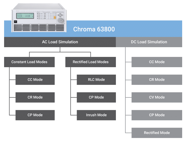
Programmable AC Electronic Load – 63800
Chroma 63800 AC Electronic Loads can simulate a variety of load conditions under high crest factor and varying power factors with real time compensation even when the voltage waveform is distorted. This unique feature provides real world simulation capabilities and prevents overstressing the instrument resulting in reliable and unbiased test results.
Key Features
- Datasheet
- Power Rating:1800W/3600W/4500W
- Voltage Range: 50V – 350Vrms
- Current Range: Up to 45Arms
- Peak Current: Up to 135A
- Frequency Range: 45 to 440Hz, DC
- Crest Factor Range: 1.414 to 5.0
- Standard GPIB and RS232 interfaces
- Parallel units for higher power or synchronize for three phase operation
- Maximum paralleled power: 22.5KW single phase / 67.5KW three phase
Description
The 63800’s state of the art design uses DSP technology to simulate non-linear rectified loads with its unique RLC operation mode. This mode improves stability by detecting the impedance of the UUT and dynamically adjusting the load’s control bandwidth to ensure system stability.
Available comprehensive measurements allow users to monitor the output performance of the UUT. Additionally, voltage & current signals can be routed to an oscilloscope through built in analog outputs. The instrument’s standard GPIB/RS232 interface provides remote control & monitoring for system integration. Built-in digital outputs may also be used to control external relays for short circuit (crowbar) testing.
Chroma’s 63800 Loads feature fan speed control ensuring low acoustic noise. The diagnosis/protection functions include self diagnosis routines and protection against overpower, over-current, over-voltage and overtemperature scenarios.
Complete AC & DC Electronic Load Simulations
Chroma’s 63800 AC & DC Electronic Load is designed for both AC & DC Load Simulations. Illustrated below are the various load modes which are available:
AC Electronic Load Simulation
The Model 63800 AC & DC Electronic Load provides two unique operating modes for AC load simulation; (1) Constant Load Mode and (2) Rectified AC Load Mode. Each are described below.
Constant Load Modes
The Constant Load Modes allow users to set the following operating modes: CC, CR and CP mode. The CC and CP modes in this category allows users to program PF, CF, or both. For CR mode the PF is always set to 1. The power factor range is limited based on crest factor programmed (Shown as Figure 1). If the programmed PF is positive then the current will lead the voltage waveform. When PF is set negative, the current will lag the voltage waveform. (See below)
Figure 1: Crest Factor vs. Power Factor Control Range; CFI = I peak / I rms; PF = True power / Apparent power
Rectified AC Electronic Load Modes
The 63800 AC & DC Electronic Load provides unique capability to simulate non-linear rectified loads for a wide range of testing applications. There are three load modes available for rectified load simulations: RLC, CP and Inrush Current.
Figure 2 shows the typical model of a rectified input. Under RLC mode, users can set the RLC values to 100% and simulate the behavior of the actual UUT. Figure 3 & 4 compares the voltage and loading waveforms between the actual RLC built circuit and the simulated rectified circuit by using Chroma’s RLC load mode. The waveform obtained under CC mode with the same loading crest factor shown in Figure 5.
Figure 2: Typical Rectified Circuit
For inrush current simulation (See Figure 6), the 63800 has an Inrush Current mode that allows the user to set different inrush current amplitude and voltage phase angle where the inrush current started.
![]() |
![]() |
![]() |
![]() |
Figure 3 | Figure 4 | Figure 5 | Figure 6 |
DC Load Simulation
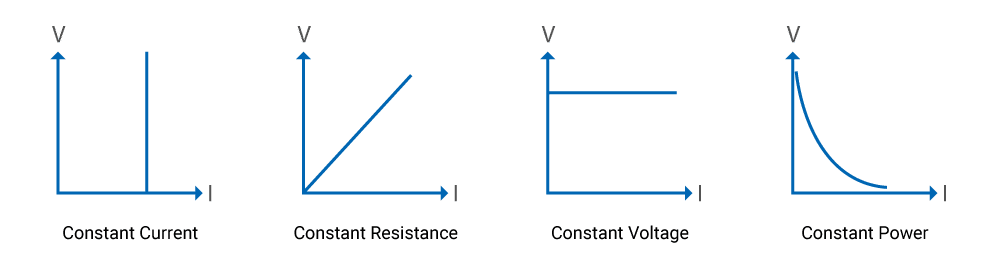
Chroma’s 63800 DC load simulation includes four load modes: constant current, constant resistance, constant voltage and constant power as depicted below. CC, CR, CP mode can be used for regulated voltage power supply testing. For battery charger, CV mode may help to check its current regulation. Many inverter designs, although its input is DC, show an input current and will show rectified pattern. This unique load mode makes the Chroma 63800 load ideal for Fuel Cell, PV module/array and Battery testing.
Comprehensive Measurements
Chroma’s 63800 Series AC & DC Electronic Loads include built-in 16-bits precision measurement circuits to measure the steady-state and transient responses for true RMS voltage, true RMS current, true power(P), apparent power(S), reactive power(Q), crest factor, power factor, THDv and peak repetitive current. In additional to these discrete measurements, two analog outputs, one for voltage and one for current, are provided as a convenient means of monitoring these signals via an external oscilloscope.
Timing Measurement
Timing parameters are critical to many products such as UPS’s Breakers and Fuses. The 63800 AC & DC Load also includes a unique timing and measurement function to measure the trip time of fuses & circuit breakers or the transfer time for UPS’s (Off-Line).
Figure 7: Transfer time for Off-Line UPS
Automatic Bandwidth Adjustment (ABA)
When the UUT, such as one shown in Figure 8, has a higher output impedance, the current waveform will not be stable without ABA. In most cases, the loading current will be oscillating and spoil the test.
Figure 8: Fixed Bandwidth
Figure 9: With ABA
Note 1: A test current will be programmed prior the actual loading defined by user for impedance detection.
Parallel / 3-Phase Control
The 63800 series provides parallel and 3-phase functions for high power and three phase applications. All the models within the 63800 series can be used together for both parallel and 3-phase functions as well as paralleled AC Load units in a 3-phase configuration, providing excellent flexibility and cost savings for the 63800 series AC load.
Figure 10: Parallel connection
Figure 11: Parallel/3-Phase Y connection
Figure 12: Parallel/3-Phase Delta connection
Auto Power Factor Correction
Setting the power factor is one of the major features to the 63800. The power factor is defined as:
Since PF is a function of real time voltage and current, traditional AC load designs assume the voltage waveform to be sinusoidal all the time, as seen Figure 13. This is not realistic because the voltage waveform may be distorted after the load is applied shown in Figure 14.
Figure 13
Figure 14
AC Electronic Load soft panel
Easy to use soft panels are available for the 63800 to allow monitoring, configuration and reporting from a PC. Contact your sales representative for more information.
See more about our software
Model | Description | |
63802 | Programmable AC Electronic Load 1800W/18A/350V | |
63803 | Programmable AC Electronic Load 3600W/36A/350V | |
63804 | Programmable AC Electronic Load 4500W/45A/350V | |
Accessories | ||
A638001 | Rack Mount Kit [63802] | |
A638002 | Rack Mount Kit [63803/63804] | |
10604 | SoftPanel KIT [63800] | |
8545-01 | Cable Kit with Terminal Resistors, 3 phase sync/Parallel Cable |
User Manuals

Manuals - 63800 Series
One time registration required in order to download documents. Register or login to continue. 12.50 MB 1578 downloadsUser Manuals for 63800 Programmable AC Electronic Loads. Available documents are: Hardware User Manual 3 Phase Parallel Setting Softpanel User Manual All files in PDF format. ...
Specifications
Brochures

Electric Vehicle Testing Solutions
Download 2758.00 KB 6694 downloadsBrochure covering Chroma Electric Vehicle testing hardware. ...

PV Inverter Testing
Download 2535 6189 downloadsBrochure highlighting the Chroma solutions for testing PV Inverters. ...