We’re going to be talking about how to simulate power line disturbances. Power line disturbances are defined as any variation in the AC voltage, whether it’s the amplitude of the voltage, a variation in the frequency, even the waveform itself.
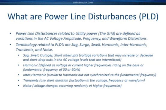
Power line disturbances also have other related terminologies such as Sag, Surge, Harmonic, Inner Harmonic, Transients, and Noise. Sag, Swell, Outages, Short Interrupts all relate to voltage variations. Harmonics refer to a change in the wave shape where a higher frequency is riding on top of the base frequency which is generally the 50 or 60Hz fundamental frequency.
Inner harmonics are very similar, but they aren’t synchronized necessarily to the base or fundamental frequency. Transients can be very short interruptions, fluctuations in voltage can also be a transient frequency or even transients in the waveform itself.
Noise is high-frequency content, also riding on the standard or base frequency voltage. It can vary to higher frequencies and be very short durations.
Chroma offers a line of AC sources which is our 61500 family. We have 10 different models available ranging from 500VA all the way up to 18KVA. You can parallel these all the way up to 90KVA as needed. They come in single-phase and three-phase output versions. We have software available that’ll make it easy for you to create these powerline disturbances.
So, I’d like to get into one of the advanced features of this model specifically. The most advanced feature is the programmable sequences, referred to as list mode. This probably is one of our best features for creating power line disturbances. You can program up to 100 sequences. Each sequence can have a different time or you can also change it to a different cycle count. The minimum sequence time is 100 microseconds or 0.1 millisecond. The minimum cycle count is 0.1 cycle.
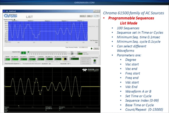
You can do different waveforms. You can program in different parameters. The parameters are basically loaded on the software for the phase shift or phase angle starting point in degrees. It has a start and end voltage. It has a start and end frequency. You can also program a start and end DC offset, and you can select between two different waveforms.
Here I’ve got it selected for cycles, so you can put in anything from multiple cycles all the way down to 0.1 cycle or one-tenth of a cycle. Down here I’ve selected and ran a test for you and I’ve captured it on my scope and you can see that we started off with three cycles at a nominal voltage. We created some harmonic distortion for one cycle. We actually dropped the voltage out for half a cycle and then we went back to a low voltage or a sag and then we went to a higher voltage or a swell. So, by doing this you can see that we can easily create all of these different types of powerline disturbances. The powerline disturbances can also be done manually on the front of the unit.
This is a screenshot of the displays. I’ve shown three different settings; voltage start and frequency start, degree setting, and waveform selection.
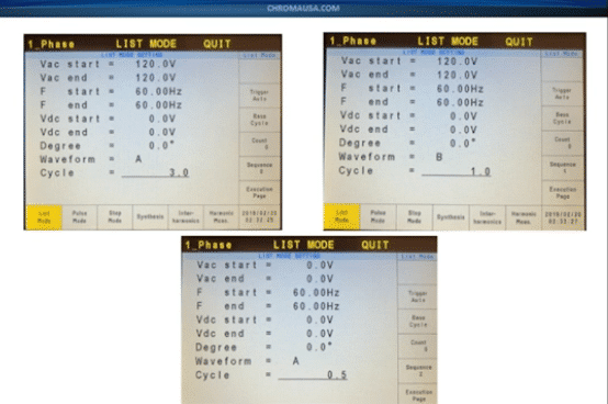
Again, you can set the base time to either milliseconds or cycles. You can set the count from anywhere from 0 to 15,000 and you can set the sequences from 0 to 99 for a total of 100 sequences.