From modest residential setups to massive commercial energy storage systems (ESS), the energy storage industry is seeing an increasing number of entrants eager to capitalize on government policies and promising trends in renewable energy. Besides raw storage capacity, one important differentiator in this market is battery cycle life. Responsible for cell balancing control and battery safety monitoring, the Battery Management System (BMS) assumes a central role in safeguarding the battery’s lifespan.
Energy storage batteries are generally not graded as highly as electric vehicle batteries. This is why an optimal battery balancing strategy is needed to avoid rapid degradation of cell consistency, which shortens cycle life and can even lead to overcharging and combustion. Another design consideration for ESS is battery module swapping functionality. This can minimize downtime for maintenance or repair, especially for grid-tied ESS, where longer online time means higher profitability. Swapping battery modules does have an impact on cell balance, however, and as the industry advances towards 1500V batteries with more and more battery strings, the challenges of cell balancing design and verification become even more pronounced.
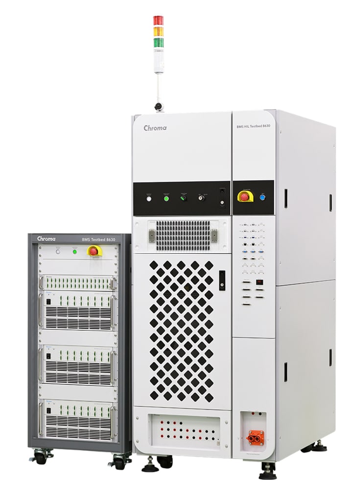
The Chroma 8630 BMS Power HIL (Hardware in the Loop) Testbed integrates various equipment simulations with a real-time control system to verify the balancing functionality of BMS. This includes single-channel currents up to 5A, suitable for testing active balancing mechanisms in a multi-channel cell simulator. Cell models can also be added in the real-time control system to emulate battery charge and discharge reactions, test the active balancing results to find the best strategy, and in turn improve product performance. Another important parameter in battery module balancing is State of Charge (SOC). This can be simulated with the testbed’s built-in equipment up to a maximum current of 900A, allowing the BMS to measure actual current and accurately calibrate SOC calculations. The cell simulator has a cell fault injection module that can simulate open and short circuit conditions at cell junctions, useful for system response verification in scenarios such as failure during active balancing.
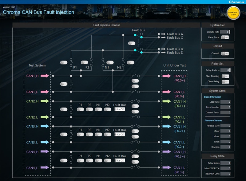
Screenshot of Chroma’s CAN bus fault injection control UI
The BMS is responsible for ensuring the safety of battery systems, constantly monitoring and responding to changes in various environmental parameters and cell conditions. Chroma’s 8630 test platform provides temperature sensor simulation, insulation impedance simulation, support for multiple communication protocols, programmable digital and analog signals, and interface fault injection to simulate and verify the protection mechanisms of the BMS in various failure modes. All these functions, including BMS communication and control, can be presented and operated using a convenient graphical user interface (GUI).
Chroma 8630 continuously monitors its own operational status through a dedicated cabinet and monitoring system, ensuring operator safety. The intuitive human-machine interface enables quick configuration of various test conditions and scenarios based on the needs of the device under test and fully supports automated testing. Already adopted and favored by many energy storage manufacturers, Chroma 8630 is a powerful and proven solution for ESS BMS development.