
As EV energy density continues to improve and CTP/CTC architectures are optimized, range anxiety has gradually eased. As a result, industry focus has now shifted toward addressing the pain points of fast charging. Companies like BYD and CATL are actively developing 5-minute fast-charging technologies (10–12C) aimed at significantly reducing charging time. In this context, three-electrode cell testing has become a key method for assessing lithium (Li) plating risks under fast-charging conditions and improving safety across the battery’s entire lifecycle.
Technical Bottlenecks and Data Accuracy Issues in Conventional Three-Electrode Testing
- Inefficient iterative testing: Traditional test equipment typically relies on constant-current pulse or step-current methods. This requires engineers to repeatedly and manually adjust the C-rate and observe the electrode potential response. With this trial-and-error approach it often takes weeks to establish fast-charging boundaries, severely delaying development timelines.
- Reference electrode (RE) lifetime and potential drift: Lithium-metal REs are prone to spontaneous reactions with the electrolyte. If the test equipment has a high leakage current, it accelerates lithium depletion, causing potential drift over time and loss of electrochemical stability, which eventually invalidates long-term testing data.
- Safety risks caused by measurement accuracy limitations: When monitoring anode potential, insufficient measurement accuracy and response speed in conventional instruments make it difficult to capture transient polarization. This can lead either to lithium plating caused by anode overpotential or overly conservative charging strategies that suppress battery performance.
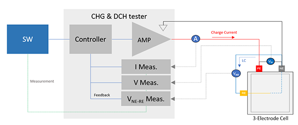
Efficient, Non-Destructive Boundary Mapping via Potentiostatic Control
- Closed-loop potentiostatic control with three-electrode configuration: The anode-to-reference electrode potential (VNE-RE) is directly clamped at the safety threshold. The system automatically and continuously adjusts the output current based on internal transport resistance. This shortens creation of a lithium plating boundary map from several weeks to just a few days, greatly improving R&D efficiency.
- High-impedance, low-leakage technology: By employing a high-impedance measurement circuit, the system achieves extremely low leakage current. This minimizes interference with the RE during measurement, reduces lithium depletion, delays potential drift, and ensures data consistency in long-cycle testing.
- High-accuracy dynamic boundary capture: With high-accuracy potential control and high-speed sampling capability, the system can instantly reflect dynamic changes in electrochemical and concentration polarization. Without damaging the anode, it enables precise construction of a highly realistic plating boundary map.
The Value of a High-Accuracy Fast-Charging R&D Test Platform
To support the advanced electrochemical analysis described above, the Chroma 17010H-6-300Hx series integrates a potentiostatic control solution with the following key specifications:
- High-accuracy potential control and high-speed sampling: Delivers ±0.01% F.S. potential control accuracy and 1ms sampling capability, ensuring precise identification of the fast-charging current threshold while avoiding overpotential risks.
- Critical >10 GΩ high-impedance technology: At the hardware level, this fundamentally solves RE potential offset and lithium depletion, significantly improving the stability of long-term testing.
- High-power output capability: Supports current output up to 4800A, meeting the extreme demands of large-capacity cells in 10–12C high-rate charging conditions.
- Efficient closed-loop R&D system: Supports dynamic Look-up Table output, allowing the generated boundary map to be directly imported for long-term aging validation, enabling a one-stop workflow from boundary assessment to strategy verification.